Hello All,
I'm currently designing a PCB where i have to place an inductor close to a Hall effect current sensor(ACS770LCB-050U-PFF-T )
Is it ok to place them close by ?Approximate distance between the two would be around 1 cm.
Hi, The sensor is used to monitor the current flowing to a rechargeable 24v battery bank from a buck converter.
It is connected in series with the LC filter.
I am not sure how sensitive is it to magnetic flux because the datasheet of the sensor has all the graphs with respect to the ambient temperature.
The maximum current would be around 15Amps,frequency would be 20Khz.
I would guess (emphasis on guess) that it's fine simply because precision sensor manufacturers usually try to warn you against anything that might cause errors and make their sensor look bad. Since they don't provide any such warnings about stray fields, and since they talk quite a bit about both electrical shielding and very close internal magnetic coupling, I'm guessing they think the sensor is reasonably well isolated from external error sources.
That said, I could be wrong, and it could also depend on exactly how much accuracy you're looking for. If in doubt, it might make sense to contact Allegro directly and ask therm. I've only had to contact them once, but they were responsive and helpful.
A thing to consider here would be the hall effect sensor type (bipolar or single pole?) and the sensor orientation with respect to the inductor. The magnetic field produced by the latter might affect the former in only certain layouts/orientations.
A thing to consider here would be the hall effect sensor type (bipolar or single pole?) and the sensor orientation with respect to the inductor. The magnetic field produced by the latter might affect the former in only certain layouts/orientations.
That's a good thought. I didn't notice anything in the datasheet that would reveal the internal sensor orientation, but that might be something that Allegro could answer.
That's a good thought. I didn't notice anything in the datasheet that would reveal the internal sensor orientation, but that might be something that Allegro could answer.
Definitely true for stand alone Hall sensors, but is it also true for current sense integrated circuits that just happen to use the Hall effect? I'm not disagreeing, I just don't know, and didn't want to make any assumptions.
Definitely true for stand alone Hall sensors, but is it also true for current sense integrated circuits that just happen to use the Hall effect? I'm not disagreeing, I just don't know, and didn't want to make any assumptions.
Ha! ... I just checked your sensor's datasheet, and it turns out that I have a couple of those suckers with me left over from a previous project. Most likely, the sensing element is oriented perpendicularly to the mounting surface, so I doubt your inductor's proximity will affect it much if you mount it parallel to it.
But I've never used an inductor installed close to a sensor such as this, so the only way to be sure about all this is to actually mount those to things in the intended arrangement and see how they behave.
And btw, feel free to disagree with me anytime you like. I'm not an expert, and I don't guide myself by opinions but rather by facts. I like to keep my ego in check ... it's already the size I want it to be, and I try to do my best to keep it from growing any further.
Ha! ... I just checked your sensor's datasheet, and it turns out that I have a couple of those suckers with me left over from a previous project. Most likely, the sensing element is oriented perpendicularly to the mounting surface, so I doubt your inductor's proximity will affect it much if you mount it parallel to it.
But I've never used an inductor installed close to a sensor such as this, so the only way to be sure about all this is to actually mount those to things in the intended arrangement and see how they behave.
Just to be clear, not my sensor - l just joined the discussion to brainstorm. I love Hall effect sensors. There are a lot of really cool things in the realm of electronics, but for some reason Hall effect sensors are especially magical to me!
Just to be clear, not my sensor - l just joined the discussion to brainstorm. I love Hall effect sensors. There are a lot of really cool things in the realm of electronics, but for some reason Hall effect sensors are especially magical to me!
I have written a mail to Allegromicro about this issue and i am still waiting for a reply.In the mean time i did a few experiments to check the same.
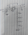
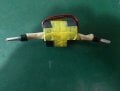
I made up a test circuit passing 1 amps of current.Attached with this post.
I have a powerful permanent magnet available,when i brought it close to the sensor,i got huge deviations in readings,i tried the same in all directions all around the sensor trying to find a suitable spot from which it effect of the magnet would be minimum but it showed deviations from all sides.
The inductor carrying around 10 amps of current's magnetic field may not be as strong as the permanent magnets,but i think it is safe to assume that some deviations in readings are to be expected.
For now i think these are my options:
1.Placing the sensor on the bottom side of the PCB and the inductor on the top with a ground plane in between may help to reduce the effect of the inductor on the sensor.
2.Also is there any way to shield the inductor ?I think i read some where that if the inductor wrapped in a metal foil,it reduces the magnetic field strength? can someone please confirm this?
3.Moving the inductor as far away as possible from the sensor using cables/wires.
Any other suggestions would be welcome.
Many thanks,
AK
I have written a mail to Allegromicro about this issue and i am still waiting for a reply.In the mean time i did a few experiments to check the same.
I made up a test circuit passing 1 amps of current.Attached with this post.
I have a powerful permanent magnet available,when i brought it close to the sensor,i got huge deviations in readings,i tried the same in all directions all around the sensor trying to find a suitable spot from which it effect of the magnet would be minimum but it showed deviations from all sides.
The inductor carrying around 10 amps of current's magnetic field may not be as strong as the permanent magnets,but i think it is safe to assume that some deviations in readings are to be expected.
For now i think these are my options:
1.Placing the sensor on the bottom side of the PCB and the inductor on the top with a ground plane in between may help to reduce the effect of the inductor on the sensor.
2.Also is there any way to shield the inductor ?I think i read some where that if the inductor wrapped in a metal foil,it reduces the magnetic field strength? can someone please confirm this?
3.Moving the inductor as far away as possible from the sensor using cables/wires.
Any other suggestions would be welcome.
Many thanks,
AK
Option #1 would be useless, I think. But option #2 is quite feasible. On the other hand, the magnetic field of a PM is normally much stronger than that of an ordinary inductor. So maybe the effect you observed is an exaggeration of what would happen with the inductor installed and operational.
Plan B would be buying a readily available shielded inductor:
Option #1 would be useless, I think. But option #2 is quite feasible. On the other hand, the magnetic field of a PM is normally much stronger than that of an ordinary inductor. So maybe the effect you observed is an exaggeration of what would happen with the inductor installed and operational.
Plan B would be buy a readily available shielded inductor:
I also did a little research on magnetic shielding recently and can confirm that copper does essentially nothing to magnetic fields, unless they're fast-moving RF electromagnetic waves. For slower, or static, magnetic fields copper is effectively transparent (which in my case was good news.)
 Facebook
 Google
 GitHub
 Linkedin
")