 Facebook
 Google
 GitHub
 Linkedin
Hey all,
I've been trying to build an EEG. It's been a very steep learning curve for me from stepping up from my usual Arduino/programming projects.
Right now, I'm trying to get my INA332 to display 'SOMETHING' somewhat resembling an EEG signal.
Seeing as how ECG is very similar to EEG, after failing to produce results, I resorted to attaching the electrodes to my chest to hopefully see a low Hz signal of something...but to no avail still.
So far I'm rocking a 1000 Gain signal supposedly on the INA332, I put two electrodes for the difference signal on my head (or chest since it's not working), and the GND electrode to my ear (or right leg for ECG testing).
The red jumper cable is my +V, and the black is the -V, which I have set to around 2.3-2.7 Volts (my single supply EVENTEK KPS305D)
The Grey probe is going into my RIGOL DS1054 as my main output, the other two black probes are going there too, and are simply testing the signals coming in from my electrodes. The electrodes are labeled with the Duct tape, and are EEG quality.
I'm following the example on the INA332 datasheet for the basic setup (http://www.ti.com/lit/ds/sbos216b/sbos216b.pdf) Page 9 Figure 1.
And setting the resistors to get a gain of 1k....2Mohm, and 10kohm.
The 2 Caps are both .1 microf.
There is an 8 pin SMD to breadboard adapter in the center with the INA332
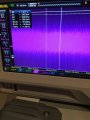
As you can see by the output waveform I attached, I can't find anything discernible at a low Hz frequency range, unless I look at these random spikes...which are essentially all over, and I don't know whether any of those spikes are attributable to real data, noise, or something I connected incorrectly. (that image was taken when the two electrodes are on my head, the other on my ear)
The arduino it's connected to isn't connected to anything, I just found when the GND from it is connected to the GND on my board it helps with noise.
I have some OPA2374's around as well (though I'm avoiding using them because I have the hardest time in the world soldering these components, as you can tell by the 8 pin adapter attached to the center of the board), but I'm not using them just yet because I can't even tell if this is working so far or not.
So here's my questions:
1. are my +V -V set up correctly to get the positive and negative swing on this device? I'm not entirely sure how to use the REF pin, if I even need to at all.
2. Is the signal I'm getting just a ton of garbage? Or are my waveforms hidden in there somewhere? Like I said, I try connecting it to my chest to get an ECG signal because they may be easier to distinguish, but I don't get much of a difference in readability.
3. Is the gain too low? I thought a gain of 1k should be enough to get atleast SOMETHING I'm looking for, or atleast distinguishable. I was going to put one of the OPA's on later to bring it to a microC's level. I know most EEG's use a 10k gain, but seeing as how I'm not even get ECG signals, it makes me think it's more of a connection issue than anything else.
4. Is there anything I can do to make these SMD components adapt to this board better? Do people hire people to do this, because I can't solder these components to fit the pin adapters to save my life.
5. Are there electronics prototyping consultants that can help me with things like this (I'm in southern California)? I respect the fact that I can get help from this forum, but for future projects it would be a godsend to have a helping hand.
6. Anything else that seems to be an issue with what I'm doing please let me know.
Any recommendations are appreciated so greatly, as this project means a ton to me.
I've been trying to build an EEG. It's been a very steep learning curve for me from stepping up from my usual Arduino/programming projects.
Right now, I'm trying to get my INA332 to display 'SOMETHING' somewhat resembling an EEG signal.
Seeing as how ECG is very similar to EEG, after failing to produce results, I resorted to attaching the electrodes to my chest to hopefully see a low Hz signal of something...but to no avail still.
So far I'm rocking a 1000 Gain signal supposedly on the INA332, I put two electrodes for the difference signal on my head (or chest since it's not working), and the GND electrode to my ear (or right leg for ECG testing).
The red jumper cable is my +V, and the black is the -V, which I have set to around 2.3-2.7 Volts (my single supply EVENTEK KPS305D)
The Grey probe is going into my RIGOL DS1054 as my main output, the other two black probes are going there too, and are simply testing the signals coming in from my electrodes. The electrodes are labeled with the Duct tape, and are EEG quality.
I'm following the example on the INA332 datasheet for the basic setup (http://www.ti.com/lit/ds/sbos216b/sbos216b.pdf) Page 9 Figure 1.
And setting the resistors to get a gain of 1k....2Mohm, and 10kohm.
The 2 Caps are both .1 microf.
There is an 8 pin SMD to breadboard adapter in the center with the INA332
As you can see by the output waveform I attached, I can't find anything discernible at a low Hz frequency range, unless I look at these random spikes...which are essentially all over, and I don't know whether any of those spikes are attributable to real data, noise, or something I connected incorrectly. (that image was taken when the two electrodes are on my head, the other on my ear)
The arduino it's connected to isn't connected to anything, I just found when the GND from it is connected to the GND on my board it helps with noise.
I have some OPA2374's around as well (though I'm avoiding using them because I have the hardest time in the world soldering these components, as you can tell by the 8 pin adapter attached to the center of the board), but I'm not using them just yet because I can't even tell if this is working so far or not.
So here's my questions:
1. are my +V -V set up correctly to get the positive and negative swing on this device? I'm not entirely sure how to use the REF pin, if I even need to at all.
2. Is the signal I'm getting just a ton of garbage? Or are my waveforms hidden in there somewhere? Like I said, I try connecting it to my chest to get an ECG signal because they may be easier to distinguish, but I don't get much of a difference in readability.
3. Is the gain too low? I thought a gain of 1k should be enough to get atleast SOMETHING I'm looking for, or atleast distinguishable. I was going to put one of the OPA's on later to bring it to a microC's level. I know most EEG's use a 10k gain, but seeing as how I'm not even get ECG signals, it makes me think it's more of a connection issue than anything else.
4. Is there anything I can do to make these SMD components adapt to this board better? Do people hire people to do this, because I can't solder these components to fit the pin adapters to save my life.
5. Are there electronics prototyping consultants that can help me with things like this (I'm in southern California)? I respect the fact that I can get help from this forum, but for future projects it would be a godsend to have a helping hand.
6. Anything else that seems to be an issue with what I'm doing please let me know.
Any recommendations are appreciated so greatly, as this project means a ton to me.
Attachments
-
 146.1 KB Views: 17
 -
 170.2 KB Views: 17
 -
 209.9 KB Views: 18


