 Facebook
 Google
 GitHub
 Linkedin
My test setup:
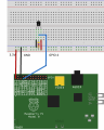
Raspberry Pi (capable of supplying 5v and 3.3v)
DS18B20 temp sensor
4.7k resistor
My future final version:
Same as above but with 10 DS18B20 sensors all running off GPIO pin 4, located up to 15 feet away running over individual cat6 patch cables.
See attached picture for how it is wired up.
Everything works in my initial test environment on a breadboard with a single sensor.
My knowledge is pretty pathetic, I'm just fumbling in the dark, but I'm learning. I became worried the distance would be a problem (this is how big of a noob I am, I'm proud of myself for thinking about the increase in resistance over a distance...) So I did a real test and things don't work so well once I add in 15+ feet of wire and some couplers/connectors/RJ45 jacks and solder.
I've done some reading and there's a lot of conflicting information, one person says add 5v, the next person says the Pi can't handle 5v on the GPIO pin as one example. Some people say to buy a $15 part and convert the signal... Not something I understand yet or really want to pay $15 x 10 for all the sensors. I don't know how it will change my code either.
To me, it seems like it should be possible to power a circuit with whatever voltage I want, even if it's 12v (which I know the DS18B can't handle, just an example) from an external source and step down the voltage before it gets back to the GPIO. Maybe I'm crazy, having the resistor hooked up in such a fashion does worry me that it would restrict me in how I supplied power.
Also, an idea of a potentiometer sounded like a good idea (in my head). I could dial it down to a functional level depending on the distance. Each sensor would have it's own potentiometer.
Maybe supply 5V to the VCC and still link the 3.3v to the data? I'm just grasping now... Thanks all for a good smack over the head.
Attachments
-
 718.2 KB Views: 6
")


