Drag strip lights and counter

Thread Starter

Briguy81

Joined Apr 11, 2019
10
Hello all
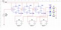
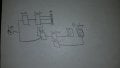
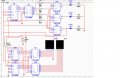
I am trying to design a circuit that will drive 3 leds (red,yellow,green) in a way that mimics whats done on a drag strip. It doesn't matter if the led stays on but they must go red yellow green. Then when the green led lights this signal will start the count for the second circuit that will count from 0 to 9.9 seconds using a 7 segment display. Right now Im having troubles just getti g the circuit for the leds to light in order. I tried using JK flip flops but that didnt work. Now Im trying to hook up a 74ls160n chip and Imgetting errors. Im using multisim and I can also only use 1 clock for this project.
 

djsfantasi

Joined Apr 11, 2010
9,237
Do you have to do it this way? Can you code?

If you can code, this is a perfect project for a microprocessor. I’m familiar with Arduinos. But, the base model has more than you need. A Nano might be a good choice and it costs $20. I’ve also used ATTiny processors. And it has enough inputs/outputs for your project without many features of its big brothers that you don’t need. It costs a couple of $, but for your first project you need a programmer. SparkFun sells one for about $15 that connects directly to your laptop or PC. In both cases, the development environment used to write the code and upload it into the microprocessor. That’s FREE.

If this interests you, I can provide more detailed information.

UPDATE: I just saw that you wanted a seven segment display. That would require more output pins than are available on the ATTiny. An Uno would be better. The best of both worlds would use external circuitry for the display and use the Uno as a clock. Through code, you can have as many “clocks” as you want.
 

Thread Starter

Briguy81

Joined Apr 11, 2019
10
I am a student and an older one at that. I can not code and for this project we must do it this way. My instructor suggested using a counter feeding a decoder. Im trying to do this but not having any luck.
 

AnalogKid

Joined Aug 1, 2013
12,086
To start, look up the data sheet for the CD4017. It is effectively a counter and decoder all-in-one. It won't work for driving the displays, but is perfect for the LEDs. Note that its outputs cannot drive the LEDs directly, but that is true for most logic chips.

ak
 

djsfantasi

Joined Apr 11, 2010
9,237
Where do I find that?
Don’t worry. The moderators will move it if they agree with me.

Thanks for responding to my post. It clarifies your problem fit me.

Take a look at the CD40160 4 bit binary counter. You can use (two of) these to count for the displays.

Their output is BCD. Your displays are 7-segment displays. So I recommend that you look at the CD4017 CD4511. It is a BCD to 7-segment decoder.

As far as the issue you have, believing that you need two clocks, I think you only need one. You look at the two clock rates desired and find a common factor between them. Then, you click the system at the faster rate that’s some multiple of the common factor. You “divide down” by some integer amount using a counter, to get the clock rate for the LEDs. Then, you also divide down the clock to get the clock rate for the display. This is probably 10Hz as your display shows tenths if a second.

Make sense?

Note: corrected the BCD to 7-segment decider chip.
 
Last edited:

Thread Starter

Briguy81

Joined Apr 11, 2019
10
Im only allowed to use one clock. I havnt even started working on the 7 segment display part as I haven't been able to get the LED portion to work right. I understand (or think I do) which ics i want to use but getting the leds to work properly has been an issue. The chip you mentioned isnt in my version of multisim. My original circuit used 3 jk flip flops. That counter worked but I didnt know how to latch the led to stay on so they just kept counting from 000 to 111. Thank you for your input though. I do appreciate it.
 

djsfantasi

Joined Apr 11, 2010
9,237
But I described how to use one clock.

The 4017 with a clock should make sequencing the LEDs easy.

What are the errors you are getting for a 74160 in multisim?

I see you haven’t posted any schematics. They would help immensely.
 

Thread Starter

Briguy81

Joined Apr 11, 2019
10
I haven't posted any schematics because I keep deleting my project and trying something else. The big error I had in multisim was because I didn't have the IC connected properly. Right now I have gone back to the 3 jk flip flops connected to sr flip flops. The leds come on and stay on. Now Im trying to find the chip I used before to divide the frequency so I can slow down how fast the keds turn on.
 

djsfantasi

Joined Apr 11, 2010
9,237
The 74160 should be able to divide the frequency down.

Even if the project doesn’t work, post the schematic anyway. It helps us see how you’re thinking and allows you to get feedback on your next iteration.
 

AnalogKid

Joined Aug 1, 2013
12,086
Since this is homework, enough with the part numbers. My advice:

Roam around online and find a site with the CMOS 4000 series parts described in function tables, select the parts that you think will work in your design, sketch them into a block diagram (no need for pin-to-pin wiring yet), and let's see if you have a topology that will meet your needs.

ak

Hint: CMOS4000
 

AnalogKid

Joined Aug 1, 2013
12,086
I haven't posted any schematics because I keep deleting my project and trying something else.
Cart before horse.

Start with a block diagram. Assign each major circuit function to a block. Define the signals that go from block to block. Work and rework this until you have captured all of the project requirements. Sure, in a fully optimized design you might save a few parts because something in the middle of this section over here can be used in that section over there, but you're not at that stage yet.

The hardest part of any project is getting the *question* right. The block diagram is just that - a statement of the question. Filling in the box details is the answer part, and it will be WAY easier if you have a decent question to work with. This sounds like it takes a lot of time, but down the road it saves way more time in not having to redo stuff because of some missed relationship. My company got a written spec from a military contractor for a sub-system, maybe 100 pages. We started going back and forth with them on the details to make sure everything was clear. Three *months* later, we had a 150 page spec (the question) everyone agreed on, and we could start on the answer. That effort took six months off of the development/engineering/production timeline.

ak
 

Thread Starter

Briguy81

Joined Apr 11, 2019
10
This is sort of what Im going for. My instructor suggested using a counter and a decoder to drive the LEDs. That part I havnt got to work but using JK flip flops works but its too fast. As far as the second part with the seven segment displays I havnt even begun working on that.
 

Attachments

AnalogKid

Joined Aug 1, 2013
12,086
The arrangement of drag strip lights is called a christmas tree, and there are plenty of examples on the web. I strongly urge you NOT to search them, and stick with developing your own circuit.

If you are stuck with a 1 kHz clock, then decide how long you want the christmas tree light intervals to be, and what a circuit needs to do to get there.

ak
 
Top