Doubt with Encoder Binary Decimal

Thread Starter

crf_h0m3r

Joined May 14, 2012
6
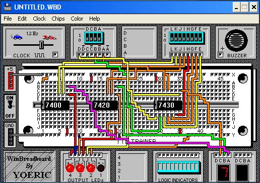
I have this little problem to create a Binary Encoder Decimal with program WinbreadBoard. The image was related to what I got to do.

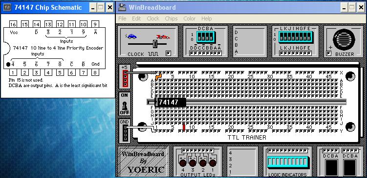
The problem is that I do not know how to put it in digital protoboard. This is different ICs or is one? All these keys .. WinBreadboard only has the ABCD (and their negations)
If a single IC, where IC is this? How do I find? I suspect that is a NAND (Not AND).
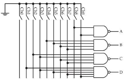


It was recommended the following ICs: 7400, 7420 and 7430. But for sure I'm doing something wrong, because the LED panels show the values ​​F and C, should be 0 and 0, since the bits are zero. \/
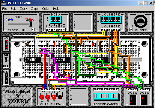


I wonder where I am wrong in this circuit.

Sorry, for my poor english.

Thanks for all.
 
Last edited:

MrChips

Joined Oct 2, 2009
35,117
You have some wrong connections.
But more importantly, you need AND gates, not NAND gates.
You can invert the outputs of the NAND gates using inverters.
 

Thread Starter

crf_h0m3r

Joined May 14, 2012
6
You have some wrong connections.
But more importantly, you need AND gates, not NAND gates.
You can invert the outputs of the NAND gates using inverters.
Why use a port "AND" + "INVERTER" if I can directly use a port "NOT AND"? And which ports you suggest?
 
Last edited:

bretm

Joined Feb 6, 2012
152
Example of wrong connections: both of the green wires going to the "C and D" terminals of the second display come from the same pin of one of the IC's, so they'll always have the same binary value. That display will only show C (1100) or 0 (0000). Similar problem with A/B and C/D on the first display.

Remember that all 5 breadboard holes in the same column are electrically connected.
 

Thread Starter

crf_h0m3r

Joined May 14, 2012
6
Example of wrong connections: both of the green wires going to the "C and D" terminals of the second display come from the same pin of one of the IC's, so they'll always have the same binary value. That display will only show C (1100) or 0 (0000). Similar problem with A/B and C/D on the first display.

Remember that all 5 breadboard holes in the same column are electrically connected.
Hmm, thanks. I would have to pull only a single wire to the display, right? At least the circuits are right?
 
Last edited:

Thread Starter

crf_h0m3r

Joined May 14, 2012
6
I changed wires that has the same binary value, now the display shows number 7, when every bits are 0.


Don't understand very well. It was to appear zero, was not it?
 

bretm

Joined Feb 6, 2012
152
No, I'd expect all 1's. The original circuit you posted uses NAND instead of AND, so the outputs will all be inverted.
 

bretm

Joined Feb 6, 2012
152
That IC has inverting outputs also (pins 9, 7, 6, 14), so you'll need to invert them if you want the 7-segment to work in the simulator. The inverting inputs (pins 1-5 and 10-13) connect to the switches, but switches E through L will need to be switched on, except for the one you want. Switches A through D already have inverting outputs. I'd use non-inverting to keep everything consistent.
 

bretm

Joined Feb 6, 2012
152
But these circuits are NAND.
Yes they are, and that's the problem. They should be AND. The circuit from your original post has inverted outputs. You need non-inverted outputs to use the 7-segment display in the simulator, which means you need to use AND.

Edit, correction: The original circuit uses N/O switches to ground. The simulator uses non-floating switches that output 0 or 1. If you want to be able to turn the simulator switch to "1" to select it, you'd need AND. Otherwise all the switches except 1 of them should be 0.
 
Top