Doubt in the below circuit

Thread Starter

Electronic_Maniac

Joined Oct 26, 2017
253
Hi all,

Please find the circuit below.
upload_2019-1-3_15-36-8.png

C3 and C4 are 25V.

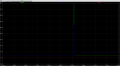
I have applied a transient pulse from 14 to 350V (for 10us) and I have captured the below waveforms.

The Greenwaveform is taken before D3 (Schottky)
Blue Waveform is taken after schottky
And the red waveform is taken across C2.


upload_2019-1-3_15-41-30.png
Can someone tell how the blue waveform voltage is low?


Thanks
 

Attachments

AlbertHall

Joined Jun 4, 2014
12,345
At the instant that the pulse rises to 350V, it is trying to charge up C3 to 350V in zero time. This means that the current is going to be very high. There is no explicit resistance in that path to limit the current. I expect LTS is dropping the voltage across the diodes.
 

Thread Starter

Electronic_Maniac

Joined Oct 26, 2017
253
At the instant that the pulse rises to 350V, it is trying to charge up C3 to 350V in zero time. This means that the current is going to be very high. There is no explicit resistance in that path to limit the current. I expect LTS is dropping the voltage across the diodes.
Wont the diode blow off/ get damaged?
 

Thread Starter

Electronic_Maniac

Joined Oct 26, 2017
253
hi EM,
Trying your asc file, I do not have model for those diodes.
E
Can you please explain me the working of the circuit in simple terms please?

What happens if I provide positive transients in the order of 350V and negative transients like 450V on the power supply?

What will happen? Will my diode get damaged? Can you tell me the current flow path also during the conditions?

Thanks
 
Top