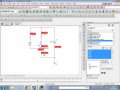
Analyzing the circuit created in Orcad get a negative current in the transistor, as the image below.
E Thread Starter eletmoraes Joined Apr 18, 2011 3 Jan 20, 2015 #1 Analyzing the circuit created in Orcad get a negative current in the transistor, as the image below. Attachments circuit1.jpg 231.8 KB Views: 78 circuit2.jpg 292.3 KB Views: 66
MikeML Joined Oct 2, 2009 5,444 Jan 20, 2015 #2 Orcad must use the convention that "current into any component pin is positive". Since in this circuit, current is actually flowing out of the emitter pin, then it puts a minus sign in front of it.
Orcad must use the convention that "current into any component pin is positive". Since in this circuit, current is actually flowing out of the emitter pin, then it puts a minus sign in front of it.
crutschow Joined Mar 14, 2008 38,568 Jan 20, 2015 #3 Most simulators use the convention that current into a device pin is positive. That may seem counter-intuitive but that's the convention.
Most simulators use the convention that current into a device pin is positive. That may seem counter-intuitive but that's the convention.
atferrari Joined Jan 6, 2004 5,017 Jan 20, 2015 #4 Not so long ago, maybe just two days, I asked the same question. Now, I feel more confident, let me tell you. Acredite!
Not so long ago, maybe just two days, I asked the same question. Now, I feel more confident, let me tell you. Acredite!
 Facebook
 Google
 GitHub
 Linkedin
 231.8 KB Views: 78
 292.3 KB Views: 66

