Facebook
 Google
 GitHub
 Linkedin
I needed to measure 3 phase current for a job recently and didn't have the clamps to do it. I rushed to eBay and bought the first good deal that popped up. I made an offer and got 3 of the clamps shown below, for $50 ea. I got rush shipping, and as soon as I got my tracking number and a guaranteed delivery date, I promised my client to be on-site the next day.

What you see there in the screenshot is all I looked at before making the purchase. The negligent eBayer that I am, I did not scroll down and look at the other pictures or descriptions. I am well familiar with the pictured clamps, also sold under Fluke brand, and others. I thought I knew exactly what I was bidding on.
But as it turns out, these are a different. They are NOT Oscilloscope probes, at least not for any oscilloscope I've ever seen. In the above pic, it looks like they have a shielded BNC connector, but had I scrolled down and looked at the other pictures, I would have seen this:


So you can imagine my dismay when I open the package at 7PM the night before I'm to be at the big hot job in the morning.
I have one of the Fluke brand clamps of the same exterior design, rated for 10mA_AC/A_AC, for use with a multimeter, and I have used it before with my scope by placing a burden resistor across the terminals to provide a mV signal.
I decided to hack these probes and see what I could see. I did not take the time to trace out the circuit or identify the components on the internal PCB; I just compared it to my Fluke clamp, which was just the CT passed straight out to the leads. When using my Fluke probe with the scope, I placed the burden resistor at the end of the banana jacks, near the scope.
I desoldered all the components on the AEMC probes PCBs, and bypassed all the traces with jumper wires, straight out to the leads. I used the internal calibration trimpots as burden resistors. I cut off those wacky 3 pin "meter" connectors (what kind of "meter" uses connectors like that anyway? Some kind of power quality/phase angle meter?) and solder/spliced BNC connectors on them. I tested them out with a resistive load up to 12A, and everything looked beautiful.
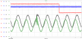
After staying up until 3AM with this crap, I went to bed and got up at 5AM to head out to the job. I set up the scope and monitored the current, and it kinda looked like crap. The traces were just really really noisy, like MHz noisy. Granted, this is not a nice resistive load, but the input to a switching power supply. But still, I expected to see pulses in the kHz range, and while they were present, they were very hard to make out and barely stood out above the noise.
So my questions are:
1. Is my theory sound? Is it "legit" to do what I've done, and if I had the same probes, designed from the factory to be scope probes, would it look any better?
2. Is my issue that the burden resistors are inside the clamp, and the whole length of the lead is carrying a minute mV signal unshielded; could I get a better result by placing the burden resistor down at the scope input like I used to with the Fluke probe?
3. Is my issue that these are strictly AC (as in, sine wave) probes and just can't provide an accurate picture of whatever this fast switching PS is doing (I should be using active AC/DC clamps)? I have verified in the past using the fluke probe with burden resistor that it will display non-sinousidal waves, like DC motor drive phas-angle SCR switching, but that is still on the order of 60Hz; this could be much faster.
4. Or is what I'm experiencing perfectly normal? Or is there some other issue I haven't thought of?
Thanks
Strantor
(BTW I think I might dig the new site theme, not sure yet)
What you see there in the screenshot is all I looked at before making the purchase. The negligent eBayer that I am, I did not scroll down and look at the other pictures or descriptions. I am well familiar with the pictured clamps, also sold under Fluke brand, and others. I thought I knew exactly what I was bidding on.
But as it turns out, these are a different. They are NOT Oscilloscope probes, at least not for any oscilloscope I've ever seen. In the above pic, it looks like they have a shielded BNC connector, but had I scrolled down and looked at the other pictures, I would have seen this:
So you can imagine my dismay when I open the package at 7PM the night before I'm to be at the big hot job in the morning.
I have one of the Fluke brand clamps of the same exterior design, rated for 10mA_AC/A_AC, for use with a multimeter, and I have used it before with my scope by placing a burden resistor across the terminals to provide a mV signal.
I decided to hack these probes and see what I could see. I did not take the time to trace out the circuit or identify the components on the internal PCB; I just compared it to my Fluke clamp, which was just the CT passed straight out to the leads. When using my Fluke probe with the scope, I placed the burden resistor at the end of the banana jacks, near the scope.
I desoldered all the components on the AEMC probes PCBs, and bypassed all the traces with jumper wires, straight out to the leads. I used the internal calibration trimpots as burden resistors. I cut off those wacky 3 pin "meter" connectors (what kind of "meter" uses connectors like that anyway? Some kind of power quality/phase angle meter?) and solder/spliced BNC connectors on them. I tested them out with a resistive load up to 12A, and everything looked beautiful.
After staying up until 3AM with this crap, I went to bed and got up at 5AM to head out to the job. I set up the scope and monitored the current, and it kinda looked like crap. The traces were just really really noisy, like MHz noisy. Granted, this is not a nice resistive load, but the input to a switching power supply. But still, I expected to see pulses in the kHz range, and while they were present, they were very hard to make out and barely stood out above the noise.
So my questions are:
1. Is my theory sound? Is it "legit" to do what I've done, and if I had the same probes, designed from the factory to be scope probes, would it look any better?
2. Is my issue that the burden resistors are inside the clamp, and the whole length of the lead is carrying a minute mV signal unshielded; could I get a better result by placing the burden resistor down at the scope input like I used to with the Fluke probe?
3. Is my issue that these are strictly AC (as in, sine wave) probes and just can't provide an accurate picture of whatever this fast switching PS is doing (I should be using active AC/DC clamps)? I have verified in the past using the fluke probe with burden resistor that it will display non-sinousidal waves, like DC motor drive phas-angle SCR switching, but that is still on the order of 60Hz; this could be much faster.
4. Or is what I'm experiencing perfectly normal? Or is there some other issue I haven't thought of?
Thanks
Strantor
(BTW I think I might dig the new site theme, not sure yet)