Dimming high current bulb using PWM and a SMPS - solved

Thread Starter

Budreaux

Joined Oct 3, 2012
18
Hello,

I have a project that is giving me problems and I'm looking for a little insight. First of all, the disclosures. I have to try and use this method of control as much as possible. That being said, I know there may be better ways of doing this, but I ask that only those that can help with this particular method respond.

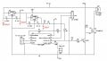
I have a 24V 250W halogen bulb that I need to be able to set to 82% and 55% brightness. I am doing this with a PWM signal of 500Hz 0-5V (see attached schematic). The power supply I am using is a Mean Well EPP-300-24 (24Vdc 300W) and according to the data sheet, it does not require a minimum current to turn on.

When I power the circuit complete, the PSU and bulb flash about every second (its like the PSU is trying to start but can't for some reason). If I disconnect the bulb, the PSU starts with no problem and is able to power an auxiliary board that is controlling other circuitry (a 12v cooling fan via a voltage regulator and other low voltage stuff).

My concern is that there is a problem between the frequency of the SMPS and the frequency with which I am trying to control the output to the lamp. Can anyone confirm this? Is there any way around this (change to the circuit, not to the method)? Thanks.pwmCircuit.jpg
 

AlbertHall

Joined Jun 4, 2014
12,345
If the PSU and the bulb work as expected with 100% PWM then I think you need a large electrolytic across the supply - perhaps 1000uF
 

ericgibbs

Joined Jan 29, 2010
18,766
Hi.
It is possible that with a 'cold' 250W lamp, the 'very low cold resistance' of the lamp is putting the 24V power supply into current limit.
E
 

Alec_t

Joined Sep 17, 2013
14,280
^ Wot they said. The cold lamp looks more like a 1000W hot lamp to the supply. An inrush current limiter, comprising an ntc thermistor in series with the lamp, might be an option.
As a side note, you would get cleaner switching of the FET (hence cooler running) if you swapped over R1 and R2; though at only 500Hz switching frequency this might not be an issue.
 

Thread Starter

Budreaux

Joined Oct 3, 2012
18
Thanks everyone for the input. I had suspected that might be the case. If I reduce the PWM signal to 15% for 5 seconds at SMPS startup, would that be enough to stop the over current or would it be a mute point since the bulb is still getting 24V?
 

crutschow

Joined Mar 14, 2008
34,281
If I reduce the PWM signal to 15% for 5 seconds at SMPS startup, would that be enough to stop the over current
That likely will work since it's only seeing the lamp 15% of the time.
Alternately can you just stop the PWM signal for the time it takes the power supply to power up?
 

ericgibbs

Joined Jan 29, 2010
18,766
hi,
I would try as Albert suggests, add a 1000uF and start up at 15% duty cycle.
E
I am assuming that you will have the PSU powered ON and the 1000uF charged before the PWM drive starts.
 

Thread Starter

Budreaux

Joined Oct 3, 2012
18
OK, I'm not sure why I didn't just do this to begin with. I have a BK Precision 8540 electronic load. So I put that in place of the lamp and set it to 2A. The circuit seems to work just fine with the 2A load on, so it would appear I do have an inrush current issue. I did notice another problem while trying to test this though, so I have a new schematic for you guys (I guess I should have led with this).

As you can see from below, I am using an ATTiny85 as my PWM generator. I placed a 5 second delay before any pwm calls, but when I power on the unit, the lamp tries to also start immediately. I added a 10k pull down resistor to the base of Q1 to keep it off, but this didn't seem to work. The rest of the program is after the 5 second delay, the pwm starts with a 15% duty cycle and holds for 5 seconds then increases to 55% over 5 seconds. This is not the intended program, just what I was testing out to see if I could get the circuit to function without the power blinking. Anyone have any further suggestions or comments on things I may have missed?pwmCircuitFull.jpg
 

AlbertHall

Joined Jun 4, 2014
12,345
For the lamp to be off Q1 should be on. The ATtiny85 pins will probably be set as inputs (Hi-Z) at power on, so the 10k resistor should pull up the base of Q1 to 5V to keep Q1 on at switch on.
 

Thread Starter

Budreaux

Joined Oct 3, 2012
18
Thanks again for the insight. I changed R1 to a pull-up on the +5V rail, but the lamp still tries to turn on when power is applied to the circuit. I have a 24v 2w bulb so I put that in place and the lamp does indeed turn on right from the start. I did find an error in my PWM signal (I had the time on/time off switched around - so it was basically trying to come on at 250W to start) so after fixing this, the circuit works as expected with the 2W lamp (with the exception of the lamp turning on right away), but still stutters with the 250W lamp. Any other suggestions?
 

Thread Starter

Budreaux

Joined Oct 3, 2012
18
Alec, D4 has an internal pull-up set at startup.

Eric, thanks for the edit. Are those electrolytic or ceramic (MLCC) caps. I have both flavors, just want to be sure I'm using the correct type.
 

Thread Starter

Budreaux

Joined Oct 3, 2012
18
OK, I made some changes to my program. I set the PWM signal to full on (255 - range is 0-255) immediately after setting it to an output (as per Alberts suggestion) and set a warm-up loop to gradually lower the PWM to 115 by 5 over 5 seconds. The SMPS now starts up immediately, but as soon as the warm up loop starts, the SMPS starts to go into over current protection. It only does this a couple of times and then either starts up correctly, or the lamp gets stuck on at a lower output (looks like somewhere around 80W or so) and does nothing else (the high/low switch has no effect on the lamp output). This may be caused by the SMPS dropping power and the micro getting stuck (glitching) so perhaps I need a cap somewhere on the 5V rail to act as a makeshift battery for the micro once it starts up. Ultimately, I'd rather just figure out how to lessen the inrush current.
 
Top