Digital Radar Speedometer (Stupid Lidar circuit)

Thread Starter

Albert Einstein

Joined Nov 20, 2016
2
Hello everybody,

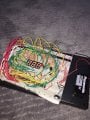
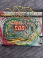
I found this circuit and I do not know their validity.

I've built this circuit on the breadborad but when I turn it ON, the seven sigma display begin to decline gradually.

The voltage output from the voltage regulator is 5 V and when I turn it ON it goes to 2.5 V.


Second thing, what is the proper transmitter and receiver if this circuit is perfect :)

But I do not think so :)


Thank you for all ;)


"I have not failed. I've just found 10000 ways that won't work." - Thomas A. Edison
 

Attachments

ericgibbs

Joined Jan 29, 2010
18,734
hi AE,
The main problem is the inter socket capacitance of the project board and wiring inductance/capacitance of the links, which are far in excess of the 2pf and 3pf, 1uH values in the circuit.
I will look over the circuit for other problems.

The overload LED detector is incorrectly named, it is an over range indicator.

E
 

AlbertHall

Joined Jun 4, 2014
12,338
Are you powering this with a 9V block type battery (PP3, 6LR61)? If so this is probably your problem with the falling supply voltage as they can supply only limited current. Check the battery voltage while the circuit is connected.
 

jpanhalt

Joined Jan 18, 2008
11,087
That circuit has been around a long time. As I recall, I first saw it about 10 years ago. It has a reputation as not working, except under very narrowly defined and unrealistic conditions. At the time, I was interested in such a project and came up with several links to actual working devices. Unfortunately, the link to the most attractive of those designs is no longer valid.

Here is a starter:
http://www.elexp.com/t_SpeedofLight.htm

I have also attached the document and its zipped code from the previously mentioned broken link that I downloaded at the time.

John
 

Attachments

Alec_t

Joined Sep 17, 2013
14,263
I don't see how the post #1 circuit can possibly work. If the 'laser diode' used for the Rx has a Vf in the range 0V to 3V then the input to the 74AS08 will be permanently above the logic 1 threshold of the gate. Also, the Tx LED is being pulsed with around 30-100mA of current by the 74AS04; which is unlikely to give the '90m' range claimed in the absence of an amplifier before the gate in the Rx.
 

DickCappels

Joined Aug 21, 2008
10,138
There is a second laser diode that has current going through it.

I did not spot any bypass capacitors on your breadboard. Without bypass capacitors the circuit is unlikely to work at all.

Echoing ericgibbs's comment in post #12: those plug-in breadboards are no good for high speed circuits.
 
Top