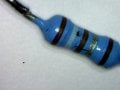
They look like brown,white,brown,silver,brown. From the calculator looks like it is 1.91 ohms. Could it be so? I wonder where could I find such resistor value.
It's part of a circuit of a small dc power supply (230v->12V). It's connected to the source pin of a N1NK80Z (guess a switch to the main transformer component). The mosfet also looks like it's shorted.
PS: I know it's stupid to try to repair such an inexpensive power supply, I'm just trying to learn.
OK, trying to learn is never stupid.
The only way to be sure of that resistor value would be a Ohm meter test.
The problem with viewing colours on a TFT monitor screen they can look different from monitor to monitor, depending on the users settings.
E
BTW:
Can you post a clip image from the circuit diagram section, that shows that resistor.??
Thank you Eric, I tried to draw a circuit and I've also attached a few pics. I know they don't help much understanding the circuit but I tried to be fast.
Unfortunately the resistor was blown (I can see small cracks in the resistor's shell and with the multimeter it shows a few megohms when I tried to measure it).
Another thing that worries me is that the mosfet looks like it's shorted (source and drain are always shorted), but I guess that's not a big deal if I don't do anything stupid with the power supply output...
Eric, do you think it would be safe to replace with a metal film resistor of the same value at least for testing if that's the only issue with the circuit?
hi,
Providing it is the correct value and tolerance ie: 1% it will be OK.
It appears to be used in a current sensing circuit, which means the value and tolerance must be correct in order to set the correct current value.
Why do you think the resistor is at fault.? the photo does not show any damage due to over heating etc.
E
EDIT:
The soldering of the resistor looks very poor, is it making contact with the surface PCB track.??
The resistor was blown (I can see small cracks in the resistor's shell with a microscope - I've uploaded a pic). I also can't measure any actual resistance with the ohmmeter(it reads 4Mohms). Both sides of the resistor soldering had continuity with the connected components.
Thank you for your time!
I'll change the resistor and will check if it works.
hi nics,
I can see the damage on the resistor, shown in that last image.
Be aware the resistor may have failed because of a fault in another section of the circuit.!
I go through this all the time here. To ME the colors look like Black / Grey / Black / Silver / Black. I AM known to be somewhat color blind - they say "Red / Greed Deficient" which makes it hard for me to determine resistor values based on color. However, with enough of the color and plenty of light I can usually call a color correctly. However, on my monitor those are the colors I'm seeing.
I have to agree, taking one leg of the resistor out of the circuit and testing its value is the best way to determine it's resistance.
Even without disconnecting the resistor you can learn a lot with a resistance measurement. If tyhe meter shows about 2 ohms then the value is probably 1.9 ohms. If the value reads very high, then the resistor is probably failed. Next question is why a 1% resistor in a cheap power supply? And the question about repairing a cheap supply depends on how much you need whatever it was doing before it failed. That is the ultimate question.
 Facebook
 Google
 GitHub
 Linkedin


")