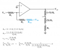
Determine gain for values of x

Thread Starter

CNC682

Joined Jan 23, 2015
27
Whats interesting is that if I substitute xRp+R3 with the proper representation of the lower arm, i.e R2 // (xRp + R3), my results from post #20 are exactly halved. Other than that I'm not sure how to determine the actual value unless I can only approximate.
 

The Electrician

Joined Oct 9, 2007
2,986
Whats interesting is that if I substitute xRp+R3 with the proper representation of the lower arm, i.e R2 // (xRp + R3), my results from post #20 are exactly halved. Other than that I'm not sure how to determine the actual value unless I can only approximate.
From what you say, I assume you did this:

Vout / Vin = - (R2/R1) * (Rp + R3) /(R2 || (x*Rp + R3))

But that's not enough. You have to consider the whole divider; the Rp+R3 part (numerator) has to include the same parallel combination like this:

Vout / Vin = - (R2/R1) * (Rp*(1-x) + (R2 || (x*Rp + R3)) /(R2 || (x*Rp + R3))
 

MrAl

Joined Jun 17, 2014
13,769
Hi,

I dont know why you guys are making this seem so complicated. The simpler op amp model to use here is the current model, not the voltage model. The voltage model brings in another variable which we can get by without if we use the current model.

Again, for the third time now, the current through R1 is the SAME as the current through R2, and the inverting terminal node is assumed to be at zero volts. That immediately tells us the voltage at the arm of the pot with respect to the input voltage Vin.
Once we know the voltage at the arm of the pot, we almost have the whole thing solved :)

No nodal analysis needed.
 

RBR1317

Joined Nov 13, 2010
715
How would you represent the load resistor?
There is no load resistor, all I see is a feedback network for which you can find the Thevenin equivalent. (The equation for parallel resistance: product over sum. The equation for voltage division.)
Then use the standard equation for summing currents at a virtual ground input to an op-amp, substitute the Thevenin derivations, and you get an equation for which you can solve for Vout/Vin as a function of X. That expression will be exact for all values of X.
RP-feedback.png
 

MrAl

Joined Jun 17, 2014
13,769
Hi,


This seems must simpler to me because of all the things we know before we even start.

1. We know the inverting terminal is at zero volts.
2. We know iR2=iR1, therefore iR2=Vin/R1, therefore Varm=R2*iR2=Vin*R2/R1.

As a result, we also know:
3. We know Varm=Vin*R2/R1 so the current through the lower part of the pot plus R3 is Varm/(x*Rp+R3).
4. Since we now know this current, the current through the upper part of the pot is the sum of iUp and iR2 which is:
iUp=iR2+Varm/(x*Rp+R3)=Vin/R1+Varm/(x*Rp+R3).
5. Since we now know that current too, the voltage Vup across the upper part of the pot is (1-x)*Rp*iUp, or (1-x)*Rp*(Vin/R1+Varm/(x*Rp+R3)).
6. Vout must be the sum of Varm and Vup which is equal to:
Vout=(1-x)*Rp*(Vin/R1+Varm/(x*Rp+R3))+Varm=(1-x)*Rp*(Vin/R1+Varm/(x*Rp+R3))+Vin*R2/R1
Vout=(1-x)*Rp*(Vin/R1+Vin*(R2/R1)/(x*Rp+R3))+Vin*R2/R1.
7. Divide that by Vin to get the gain G=Vout/Vin (note Vin is in all three factors), and we get:
G=-(Rp*(1-x)*(R2/(R1*(R3+Rp*x))+1/R1)+R2/R1) (making this negative to show the output inversion).

So just by recognizing some little facts we were able to build up the solution step by step, just knowing those little facts, and we didnt even need to actually solve for any variables really. The math needed wasnt even that complicated.

One last note though....

These analyses have to be checked for a few things before concluding that we have the total analysis. A short list is:
1. Range of device voltages and currents.
2. Latchup.
3. Oscillation.

Of these #1 is probably the most important, because many times we come up with an analysis and find that the real life circuit can not function the way we thought because one or more of the voltages and/or currents has to be too high or maybe even too low.
For a circuit like this, if the gain is very high like 100 and we input 1v as Vin, the analysis would tell us that we should see 100v output. Now that's ok if the circuit can handle it, but with low voltage power supplies like plus and minus 15 volts or lower it quickly becomes obvious that this aint gonna work in real life because we cant get 100 volts output with just a 15 volt power supply :)
 
Last edited:

Thread Starter

CNC682

Joined Jan 23, 2015
27
"G=-(Rp*(1-x)*(R2/(R1*(R3+Rp*x))+1/R1)+R2/R1) (making this negative to show the output inversion)."


Should gain =-100099 when x=0? thats a lot of gain. However with x set to 1, there is zero gain.
 
Top