Facebook
 Google
 GitHub
 Linkedin
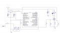
Just in process of putting together a control circuit with a PIC 18F4685 processor to control 10 solenoids/motors running off 24 volts and drawing 2 amps or less. After scanning some posts here I saw when using a bunch of Fets you need to take into account gate charge. I never have used that before and don't really know how you would calculate it but I did look up the gate capacitance (3000 pf) and calculated and saw by using my standard 10K in series with the gate it could take up to 80 us to get to full level. Peak current would only be 0.5 ma, so that wouldn't overload the PIC's output. So I guess the important thing is turn on delay, The circuit is presently using a PLC and relays so speed probably isn't too important. Am I missing anything else?
I using optocouplers on the inputs to the uP. Is there any point to use them on the outputs of the uP to the gate of the FET, the power supply to the solenoids and the uP share the same ground?
One other thing I was going to add was a small 0.2 ohm resistor in series with the source to ground (I'm using low side switching). I could then connect that to ADC i/p's and monitor current. My main concern is that if a FET goes it normally shorts and that could leave a coil on and get very warm. Is there any better ways of doing that?
Thanks
Geoff