Designing a simple audio amplifier

Thread Starter

createdtowatch worldcup

Joined Oct 4, 2018
11
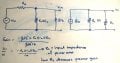
Hello guys , I'm new to amplifier design .I need to design a preamplifier to be used for amplifying guitar frequencies. The last stage is a power amplification stage but my question is how to connect the power amplifier to the preamplifier. If I use the power amplifier below from my book, its input impedance will be too low if an 8 ohm speaker is used ( Bre is low) which will decrease the gain of my preamp.Untitled.png
 

Audioguru

Joined Dec 20, 2007
11,248
Your class-A transistor has DC in its load Rc. A speaker cannot be Rc because a speaker must never have DC in it. A class-A amplifier is a heater (its transistor gets very hot even when it has no signal). Most amplifier outputs are class-AB and use two complementary transistors as emitter-followers.

What is the input from the guitar? A magnetic pickup? The preamp for a magnetic pickup is usually a vacuum tube or Jfet with an input impedance of at least 1M. The one shown is 3M. The gain of the Jfet preamp is low because the output of a magnetic pickup is high.
 

Thread Starter

createdtowatch worldcup

Joined Oct 4, 2018
11
Your class-A transistor has DC in its load Rc. A speaker cannot be Rc because a speaker must never have DC in it. A class-A amplifier is a heater (its transistor gets very hot even when it has no signal). Most amplifier outputs are class-AB and use two complementary transistors as emitter-followers.

What is the input from the guitar? A magnetic pickup? The preamp for a magnetic pickup is usually a vacuum tube or Jfet with an input impedance of at least 1M. The one shown is 3M. The gain of the Jfet preamp is low because the output of a magnetic pickup is high.
Hello, I was given to use only BJT in my project. I'm using a simple electret microphone and a 2 stage voltage divider configuration for the pre-amplifier to get a gain of 75. The input impedance of the last power stage will affect the load on my preamplifier as a result the gain will be reduced right ? I need higher output load on my preamp. Also what is the most commonly used power amplifier class for audio ?
 

Thread Starter

createdtowatch worldcup

Joined Oct 4, 2018
11
Your class-A transistor has DC in its load Rc. A speaker cannot be Rc because a speaker must never have DC in it. A class-A amplifier is a heater (its transistor gets very hot even when it has no signal). Most amplifier outputs are class-AB and use two complementary transistors as emitter-followers.

What is the input from the guitar? A magnetic pickup? The preamp for a magnetic pickup is usually a vacuum tube or Jfet with an input impedance of at least 1M. The one shown is 3M. The gain of the Jfet preamp is low because the output of a magnetic pickup is high.
I'm thinking of a power stage like the figure below. The speaker will then have no dc part and I can control the input impedance with RE.Will there be any problems in this circuit ?
 

Attachments

Thread Starter

createdtowatch worldcup

Joined Oct 4, 2018
11
Your class-A transistor has DC in its load Rc. A speaker cannot be Rc because a speaker must never have DC in it. A class-A amplifier is a heater (its transistor gets very hot even when it has no signal). Most amplifier outputs are class-AB and use two complementary transistors as emitter-followers.

What is the input from the guitar? A magnetic pickup? The preamp for a magnetic pickup is usually a vacuum tube or Jfet with an input impedance of at least 1M. The one shown is 3M. The gain of the Jfet preamp is low because the output of a magnetic pickup is high.
This was what I'm saying and I only need to use BJT
 

Attachments

Audioguru

Joined Dec 20, 2007
11,248
You need a Power Amplifier. Most power amplifiers are Class-AB. A Class-A amplifier heats with more power than its output power.

I simulated your circuit. Its output power is almost zero.
Then I reduced the resistor values 122 times for more current, increased the capacitors values and used a power transistor then got a tiny output.
Then I reduced the resistor values another 10 times and got a maximum output of only 0.72W like a cheap clock radio.
The transistor would be burning up since it would be heating with 5.3W.
The voltage gain is only 4.25 times, but it needs a voltage gain of about 125 times for a microphone input and about 1.5W output.
 

Attachments

Thread Starter

createdtowatch worldcup

Joined Oct 4, 2018
11
You need a Power Amplifier. Most power amplifiers are Class-AB. A Class-A amplifier heats with more power than its output power.

I simulated your circuit. Its output power is almost zero.
Then I reduced the resistor values 122 times for more current, increased the capacitors values and used a power transistor then got a tiny output.
Then I reduced the resistor values another 10 times and got a maximum output of only 0.72W like a cheap clock radio.
The transistor would be burning up since it would be heating with 5.3W.
The voltage gain is only 4.25 times, but it needs a voltage gain of about 125 times for a microphone input and about 1.5W output.
So I'm thinking of using a 2 stage common-emitter for the pre-amplifier stage and a class AB power amplifier to drive the 8ohm speaker.But should I place a buffer or other circuit between the preamp and poweramp so that the input impedance of the poweramp does not load/affect previous stages ?
2018-10-05_163129.png something similar to this circuit (I forgot 2 resistors before the darlington) except instead of the 8ohm, I connect the class AB power amp
 

MrChips

Joined Oct 2, 2009
30,714
You need to understand the requirements of a simple audio amplifier. This can be laid out in three stages.
Each stage has a specific function and that is to match the source to the load with the required gain and power output.

1) High impedance, high gain microphone preamp.
2) Driver stage to match the output impedance of the preamp to the input of the power amp.
3) Power amp output to drive a low impedance loud speaker.

1) The mic preamp needs to have high input impedance. It also has to amplify a very weak signal to a level of about 2V. Power level requirements are not demanding.

2) The driver stage needs to provide moderate current and voltage gain. Hence the output impedance has to be moderately low to drive the final power amp stage.

3) The power amp pushes high current into a low impedance load. Hence the power amp has to have very low output impedance, lower than that of the loudspeaker.

After you have studied all of this, you may want to add negative feedback to improve linearity and avoid thermal runaway.
 

Thread Starter

createdtowatch worldcup

Joined Oct 4, 2018
11
You need to understand the requirements of a simple audio amplifier. This can be laid out in three stages.
Each stage has a specific function and that is to match the source to the load with the required gain and power output.

1) High impedance, high gain microphone preamp.
2) Driver stage to match the output impedance of the preamp to the input of the power amp.
3) Power amp output to drive a low impedance loud speaker.

1) The mic preamp needs to have high input impedance. It also has to amplify a very weak signal to a level of about 2V. Power level requirements are not demanding.

2) The driver stage needs to provide moderate current and voltage gain. Hence the output impedance has to be moderately low to drive the final power amp stage.

3) The power amp pushes high current into a low impedance load. Hence the power amp has to have very low output impedance, lower than that of the loudspeaker.

After you have studied all of this, you may want to add negative feedback to improve linearity and avoid thermal runaway.
Can I have an example of the driver stage please. I'm thinking of a darlington common-collector am I right ?
 

Audioguru

Joined Dec 20, 2007
11,248
A simple class-AB power amplifier has complementary (NPN and PNP) output transistors and a driver transistor.
Its preamp needs a single transistor with a gain of only about 25 times for it to work well from an electret mic mounted very close to a guitar.
Here is a simple class-AB amplifier with an input impedance of about 24k and a max input of 1V peak:
 

Attachments

Thread Starter

createdtowatch worldcup

Joined Oct 4, 2018
11
A simple class-AB power amplifier has complementary (NPN and PNP) output transistors and a driver transistor.
Its preamp needs a single transistor with a gain of only about 25 times for it to work well from an electret mic mounted very close to a guitar.
Here is a simple class-AB amplifier with an input impedance of about 24k and a max input of 1V peak:
Thats great i'll try implementing this design, however for the input impedance (24k) how did you calculate that ?
 

Audioguru

Joined Dec 20, 2007
11,248
Thats great i'll try implementing this design, however for the input impedance (24k) how did you calculate that ?
I would have liked the power amp to have more voltage gain than only 5 times which is determined by the 240k feedback resistor, the 24k input resistor and the circuit but to have a higher voltage gain then the 24k resistor value must be reduced which causes obvious distortion and puts a strain on the preamp transistor. When the 24k is 10k the distortion is noticeable and when it is 4.7k then distortion is awful and the voltage gain is 23 times. 24K is pretty good but 47k will produce very low distortion and a fairly low voltage gain of only 2.6 times.

Did you understand about the bootstrapping capacitor and the two resistors that it feeds? It increases the output voltage swing by causing the base of the NPN output transistor to swing above the 12V supply voltage. The output power without the bootstrapping is only 1.0W.
 
Last edited:

Thread Starter

createdtowatch worldcup

Joined Oct 4, 2018
11
I would have liked the power amp to have more voltage gain than only 5 times which is determined by the 240k feedback resistor, the 24k input resistor and the circuit but to have a higher voltage gain then the 24k resistor value must be reduced which causes obvious distortion and puts a strain on the preamp transistor. When the 24k is 10k the distortion is noticeable and when it is 4.7k then distortion is awful and the voltage gain is 23 times. 24K is pretty good but 47k will produce very low distortion and a fairly low voltage gain of only 2.6 times.

Did you understand about the bootstrapping capacitor and the two resistors that it feeds? It increases the output voltage swing by causing the base of the NPN output transistor to swing above the 12V supply voltage. The output power without the bootstrapping is only 1.0W.
Thanks very much for the detailed explanation and your time @Audioguru I tried to understand how AB poweramps work and now I feel I finally understand your circuit (Am still a beginner though) ;) Cheers
 
This was what I'm saying and I only need to use BJT
You need a Power Amplifier. Most power amplifiers are Class-AB. A Class-A amplifier heats with more power than its output power.

I simulated your circuit. Its output power is almost zero.
Then I reduced the resistor values 122 times for more current, increased the capacitors values and used a power transistor then got a tiny output.
Then I reduced the resistor values another 10 times and got a maximum output of only 0.72W like a cheap clock radio.
The transistor would be burning up since it would be heating with 5.3W.
The voltage gain is only 4.25 times, but it needs a voltage gain of about 125 times for a microphone input and about 1.5W output.
Please @Audioguru what's the software you used in simulating his work?
 

Audioguru

Joined Dec 20, 2007
11,248
Like most people on electronics forums I use the free simulation software called LTspice XVII available at www.analog.com .

The software allows currents and temperatures higher than allowed on datasheets. The simulation for the circuit I posted shows a peak of 5V into the 8 ohms speaker which is a current of 5V/8 ohms= 625mA. The datasheets of the little 2N4401 and 2N4403 transistors it used have a maximum allowed current of 600mA and shows that they work poorly above 300mA.
The simulation uses "typical" specs for its transistors so the circuit might not work if transistors have minimum or maximum spec's.

So the designer must read the minimum and maximum spec's on the datasheets to design with the proper parts values that work with all the spec's the transistors could have.
Oh! Yeah! Thanks for this, I'm grateful.
 
Top