design a constant current source using a buck-converter

Thread Starter

deen25

Joined Oct 1, 2008
11
i need help designing a current source that can produce up to 50Amps CONSTANT current for a power cycling test rig. Input voltage is up to 10V.

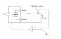
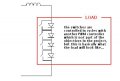
I have decided to replace the diode and switch in the buck converter with MOSFETs and (out of phase) synchronous pwm buck controller, due to the fact that i'm working with low-voltages. I'm having difficulty selecting the correct pwm controller and the MOSFETs as the gate voltages and gate charges have to be correlated and should also be able to stand for 50Amps current...

the current is measured using hall effect sensors (replacing resistors so that i don't mess with the voltage again!) and compared with a reference current. the feedback loop is all included in the pwm controller so the challenge for me is to measure the current and send the relevant data to the comparator.

with assumptions and calculations i have decided the inductor value to be 2μH...if that should help in anyway. i have to make this inductor by myself too!

suggestions and ideas are welcome !! =) i need to work on this fast....thanks alot!
 
Last edited:

Thread Starter

deen25

Joined Oct 1, 2008
11
i'm sorry for my negligence but i'm really not sure how i can upload a picture from my laptop..the insert image option ask's for a URL... ? i tried giving the address of location on my pc but it doesnt seem to be working...!
 

thingmaker3

Joined May 16, 2005
5,083
In addition to your PWM, you'll need a high-side/low-side driver. Depending on how low your frequency is and how inductive your load is, you might also need a filter.
 

scubasteve_911

Joined Dec 27, 2007
1,203
I believe this is what they do for switching constant-current LED drivers. You may want to look into those, but I don't really know what voltage/current levels you're working with. Secondly, I don't know what ripple current is tolerable.

Steve
 

Thread Starter

deen25

Joined Oct 1, 2008
11
i'm looking to take about 10% ripple current tolerance <= 5A, because as ripple current is large the inductor will be larger and bulkier..and i have build the inductor myself. Basically input supply is 10V, duty cycle assuming to take at 0.5 because output voltage is not the issue but the constant current at 50A which should be passed through the load.
 

scubasteve_911

Joined Dec 27, 2007
1,203
Deen,

The ripple current can always be taken down by increasing the PWM frequency. This will boil down to a tradeoff between switching losses and the physical size of your inductor. One more question, what kind of response do you require? This should be in form of a current slew rate, in A/s.

Your inductance value, supply voltage, and maximum PWM percentage will dictate this response time. So, if possible go with a higher voltage supply and lower inductance with a higher switching frequency. Sure, you will have a bit of switching loss, but at that power level, it will be small.

Are you sure your hall-effect sensors are good candidates? Are they fast enough? How accurate are their zero-points in terms of device-device variation? How are you setting the current, or is it fixed?

Sorry for all the questions, it may seem like a lot.

Steve
 
Last edited:

Thread Starter

deen25

Joined Oct 1, 2008
11
okey to be honest..i'm kind of lost in this whole project...my project supervisor has given me very limited info and is not willing to help further...though i'm in my final year..i dont have alot of experience working with power circuit designing..this is in fact my first..i've been more of a software person working with DSP's and ADC-DAC stuff...this is new to me and i need someone to guide me properly so that i can grasp the idea...sorry for being so negligent but i've tried all sorts of reading material and i cant get my hands on any material that will help me design this piece of hardware...!!

any suggestions as to how in a step by step method..that i can build up this circuit...? what do you think are the recommended components?...and switching frequencies?
what should i consider most of all before i start researching? my search results end up with absolutely nothing! i need to make progress on this project ASAP..

cheers!
 

SgtWookie

Joined Jul 17, 2007
22,230
i'm looking to take about 10% ripple current tolerance <= 5A, because as ripple current is large the inductor will be larger and bulkier..and i have build the inductor myself.
Tell us about this inductor you've built.
What do you estimate it's inductance is?
Wire gauge, number of turns, length?
What was the diameter of the mandrel it was wound on?
Or did you use a ferrite toroidal core? If so, what manufacturer, material, and part number?

Basically input supply is 10V, duty cycle assuming to take at 0.5 because output voltage is not the issue but the constant current at 50A which should be passed through the load.
What information do you have about the load? Is it purely resistive, or is it reactive in some way?
 
Last edited:

Thread Starter

deen25

Joined Oct 1, 2008
11
i haven't yet built the inductor...i need to use other parameters first to calculate the inductance that will be required...which turned out to be about 2μH - this is only an estimated calculation and i haven't consulted my supervisor yet.

the load can be anythn...i was asked to assume the load will be a set of by-passed diodes (for reference sake i've attached a schematic...)

cheers!
 

Attachments

SgtWookie

Joined Jul 17, 2007
22,230
Take a look at Linear Technology's LTC4447 - High Speed Synchronous N-Channel MOSFET Driver.
Link: http://www.linear.com/pc/productDetail.jsp?navId=H0,C1,C1003,C1142,C1041,P85072

That'll give you a start for the high/low side N-ch MOSFET drivers.

As far as the Hall-effect sensor - I think that's adding a bit much to the complexity angle. One foot of AWG 10 stranded copper wire with 50A current flowing through it will have a 50mV drop. One foot of AWG 6 stranded copper wire with 50A flowing through it will have a 20mV drop.
Here's a wire resistance calculator for you:
http://www.stealth316.com/2-wire-resistance.htm
[eta]
Oh, and you might inquire of your project supervisor if he had any particular PWM frequencies in mind... like perhaps 42.8kHz, or something else related to Keely, Meyer or Boyce concepts.
 
Last edited:

SgtWookie

Joined Jul 17, 2007
22,230
Well, haven't heard back from you yet, but decided to fiddle with it anyway.

The basic circuit is the LTC4447 driving a couple of IRF1406 N-ch power MOSFETs. Unfortunately, the LTC4447 only gets the gates up to Vgs=6v; that's fine for logic input MOSFETs, but not for standard power MOSFETs. As a result, I'm considering Microchip's MCP14628 instead - however, they don't supply a SPICE model for it. In the meantime, the LTC4447 is somewhat similar, except for the gate voltage.

The inductor is 68uH. 22uH is about as low as I think it should go; below that the ripple gets excessive. Four Schottky diodes are the simulated load, along with some low values of resistance to simulate wiring. Current through the inductor (and hence the load) is shown in the simulation by the green trace.

The 555 is the PWM source (cyan trace in the simulation). The frequency and on-time varies with the control voltage input (red trace).

The LT1007 opamp supplies the control voltage input to the 555 timer. It's noninverting input is the threshold voltage (set by R9, a 1k pot), and the inverting input is a voltage representing the current through the load, smoothed by R7 and C4. When the load current is too low, the 555's control voltage is increased to give a longer ON-time output from the 555 timer.

As the voltage on the opamp's inverting input rises to that of the noninverting input, the output (control voltage) of the opamp decreases, until they are balanced.

The whole circuit could likely be simplified using a dedicated PWM controller, but I'm just using components that I have SPICE models for; and it's part of a (rather slowly) evolving design.

I've attached a graphic of the simulation, along with the LTSpice file.
You can download LTSpice from Linear Technology's website for free.
http://www.linear.com
After you install it, download 555-PWM4.asc to your Program Files\LTC\SWCadIII directory.
 

Attachments

Thread Starter

deen25

Joined Oct 1, 2008
11
hey...thanks a lot for the information! i can understand how the circuit works...i'm sorry didn't reply earlier because i was caught up with some other coursework.

yeah, i'll download the simulation software and try it out myself...i should probably look the for the dedicated PWM controller online and find out more details about it which will make the circuit less complex...

i'll read up further and get back to you if i have any questions... thanks alot!

cheers!
 

steveb

Joined Jul 3, 2008
2,436
... i have decided the inductor value to be 2μH...if that should help in anyway. i have to make this inductor by myself too!

suggestions and ideas are welcome !! =) i need to work on this fast....thanks alot![/B]
A 2 μH inductor is small enough that you could wind it yourself using an air-core. Sure, the inductor will be a little large, but you will be avoiding nonlinear effects. I'm assuming you don't have any size constraints. You need very thick copper wire, like 6 or 8 ga.

I've attached a PDF that quickly goes through the air-core approach, and also an iron-core approach, if you don't like the air-core idea. I put this together quickly, so you will want to verify anything you use, but hopefully this speeds you up a little.

If you do decide to use an iron-core, you will have to choose and obtain a suitable core, and then estimate the nonlinear effects and core losses. A quick way to do that is go to the Micrometals website, they have free software that will help you design an ironcore coil and estimate nonlinear inductance, core losses and copper losses etc.
 

Attachments

Thread Starter

deen25

Joined Oct 1, 2008
11
hey guys! I'm sorry i've not been in touch cuz i've been out of town in the last week and also have been very ill with the flu...i'm just recovering. I need to get back to work now and start research on my project...thanks alot for all your help. i will do some further reading and get back to you all when i've collected information that i can work on. cheers!
 

Thread Starter

deen25

Joined Oct 1, 2008
11
hi guys..it's been a while...hope you all are doing well and the new years been great!...i've just finished exams and started full time work on my project..cheers to all your help!

any idea of logic level mosfet equivalent of the IRF1405? and do you think the IRF1405 is a little over specified to deal with my project...

i worked on the simulation..i have an idea of how the circuit should be...i prbly will start circuit construction next week to get started off...

many thanks,
 
Last edited:

patsak

Joined Mar 31, 2009
2
Hi,

I am working on the same kind of project, and i wanted to know what you have done since the last reply..

Actually, I am not generating yet 50A, I am concentrating to understand how I can generate a current, so for the moment I am generating only 4A. But I am interested to know what yu have done for 50A, cause I will maybe do it latter.

My aim is not only to create a constant current. I want to be able to test an electricity meter. So i want to have an image of a small voltage as a current at the output. I think you could understand it better if you are seing the picture.. I have few problems:
- the efficiency is only around 63%, so not so much
- i can only use a voltage which have a small voltage (around 0.4V) and a small frequency (2kHz)

So all the ideas are welcome, I hope somebody could help me.

Thanks

Nb: sorry for the mistakes, I am french..lol
 

Attachments

Top