Facebook
 Google
 GitHub
 Linkedin
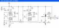
I've pieced together this circuit but I'm not sure if I've got all the connections right...
Here's what I'd like it to do:
When triggered with S1, U1 delays approx 10 secs before triggering U2. U2 then outputs a signal activating M1 for approx 3 secs before shutting of again.
Does it look workable?

Here's what I'd like it to do:
When triggered with S1, U1 delays approx 10 secs before triggering U2. U2 then outputs a signal activating M1 for approx 3 secs before shutting of again.
Does it look workable?