Decoupling capacitor

Thread Starter

matty204359

Joined Apr 6, 2011
105
suppose I have a rather large circuit with many elements that are switching, and maybe the input supply is a bit noisy. however I want to run a MCU(Microchip PIC) that will ultimately be the one controlling the switching. the basic question is can I just slap a really big tank capacitor across the voltage rail near the IC to avoid any random noise from effecting its input voltage? Is there a limit of an acceptable size? another concern was ESR of the capacitor limiting the DC current.

since the MCU will be switching at a rather high frequency some thing near 80 MHz CPU/DSP oscillator. and even higher yet the PWM peripheral modules at 120 MHz.

for example:

\(xc=\frac{1}{(2)(\pi)(f)(C)}\)

something massive like a 1 farad capacitor at a frequency of 100 MHz gives you (1/some huge number) meaning you have extremely low capacitive reactance. which would lead me to believe bigger is better! I'm still concerned with the DC ESR.

Extra info:
My goal is to implement a DC-DC buck converter, using a single chip. the single MCU/DSP, would be responsible for everything. except the power mosfets and their respective gate drivers.

Most of my concern is in the on chip ADC. noise in the input will make the reading garbage. I want to limit the buck converter to as few IC's as possible. Initially I was gonna use a precision 4.096 volt ADC reference for an external ADC. the idea of reduced complexity that a single chip controller could provide grew on me. Obviously with the DSP functionally I can do some digital filtering.
 
Last edited:

eeabe

Joined Nov 30, 2013
59
It's pretty common practice to use a variety of capacitor sizes for decoupling. Generally, capacitors of different sizes are best at decoupling different frequencies because ESR is not really constant across frequencies.

One way to do it is to put a large capacitor anywhere in the circuit, and then put small ones near the points that have high frequency current requirement, such as at the Vcc pins of an MCU, or near other IC's or switching devices.
 

ian field

Joined Oct 27, 2012
6,536
suppose I have a rather large circuit with many elements that are switching, and maybe the input supply is a bit noisy. however I want to run a MCU(Microchip PIC) that will ultimately be the one controlling the switching. the basic question is can I just slap a really big tank capacitor across the voltage rail near the IC to avoid any random noise from effecting its input voltage? Is there a limit of an acceptable size? another concern was ESR of the capacitor limiting the DC current.

since the MCU will be switching at a rather high frequency some thing near 80 MHz CPU/DSP oscillator. and even higher yet the PWM peripheral modules at 120 MHz.

for example:

\(xc=\frac{1}{(2)(\pi)(f)(C)}\)

something massive like a 1 farad capacitor at a frequency of 100 MHz gives you (1/some huge number) meaning you have extremely low capacitive reactance. which would lead me to believe bigger is better! I'm still concerned with the DC ESR.

Extra info:
My goal is to implement a DC-DC buck converter, using a single chip. the single MCU/DSP, would be responsible for everything. except the power mosfets and their respective gate drivers.

Most of my concern is in the on chip ADC. noise in the input will make the reading garbage. I want to limit the buck converter to as few IC's as possible. Initially I was gonna use a precision 4.096 volt ADC reference for an external ADC. the idea of reduced complexity that a single chip controller could provide grew on me. Obviously with the DSP functionally I can do some digital filtering.
ESR can be an issue with large electrolytics, with aluminium electrolytics; the 2 plates are usually rolled up strips of foil, so there's usually significant parasitic inductance as well.

Its common practice to have some bulk decoupling where power enters the board, and also at the opposite corner or at all 4 corners.

Usually; you should give every single chip on the board its own local decoupling capacitor, 10 - 100nF is typical, disk ceramics are good enough, but multilayer ceramic chip capacitors have the lowest ESR - some manufacturers offer resin-dipped leaded parts if you're not doing SMD layout.

I've seen brochures offering ceramic chip as high as 180uF!
 

Thread Starter

matty204359

Joined Apr 6, 2011
105
The datasheet should tell you what bypassing capacitors you need. Typically, PICs call for a 100nF at each Vss/Vdd pair.

Bob
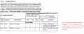
I did read that section of the data sheet

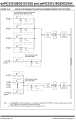
"On boards with power traces running longer than six
inches in length, it is suggested to use a tank capacitor
for integrated circuits including DSCs to supply a local
power source. The value of the tank capacitor should
be determined based on the trace resistance that connects
the power supply source to the device, and the
maximum current drawn by the device in the application.
In other words, select the tank capacitor so that it
meets the acceptable voltage sag at the device. Typical
values range from 4.7 μF to 47 μF."

I'm not really worried about the voltage sag on the actual cpu of the chip, it can handle a lot of ripple, I'm worried about the ADC voltage ripple. stable ADC voltage reference is what I'm looking for.


Attachments

alfacliff

Joined Dec 13, 2013
2,458
the normal practice is to place a .1 or so cap across the power rail at each IC. One large cap where the power comes in is usually sufficient, 100 mf or so. for that high frequency, a smaller cap shoud be used in paralell with the .1 mfd, unless the internal inductance of thde .1 is real low. a problem with caps is that they also have an inductive effect, and can be resonant at unwanted frequencies too.
cliff
 

Thread Starter

matty204359

Joined Apr 6, 2011
105
thanks guys I think I got it now.


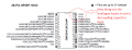
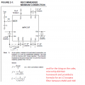
I'm gonna just put the decoupling caps on the IC pins as per Microchip's instruction and your recommendations. If that doesn't do it I might employ some sort of decade capacitor bank, ie. 0.01μ , 0.1μ, 1.0μ, 10.0μ in parallel and see how that performs.


Microchips pinout


Microchips LC filter?
 

Attachments

ian field

Joined Oct 27, 2012
6,536
thanks guys I think I got it now.


I'm gonna just put the decoupling caps on the IC pins as per Microchip's instruction and your recommendations. If that doesn't do it I might employ some sort of decade capacitor bank, ie. 0.01μ , 0.1μ, 1.0μ, 10.0μ in parallel and see how that performs.
In some demanding applications you might see about three capacitors in parallel immediately local to a supply rail pin.

You might see a 1n & 100n disc ceramic and a 10u tant, generally at least one bulk smoothing where power enters the board; 100 - 470u is often seen.

If you're working with ADCs - watch out where you ground decoupling caps - there's often both digital and analogue grounds.

Generally speaking; the decoupling capacitor traces should take the shortest possible route from the Vcc to the GND pin.
 

Thread Starter

matty204359

Joined Apr 6, 2011
105
If you're working with ADCs - watch out where you ground decoupling caps - there's often both digital and analogue grounds.
I was thinking of making it a two sided PCB and basically flooding the bottom layer with a ground plane. common ground on both analogue and digital, maybe separate them and have a star ground(single point) connection. so basically have a Dground and an Aground, but connected at a single point to keep them common.
 

ian field

Joined Oct 27, 2012
6,536
I was thinking of making it a two sided PCB and basically flooding the bottom layer with a ground plane. common ground on both analogue and digital, maybe separate them and have a star ground(single point) connection. so basically have a Dground and an Aground, but connected at a single point to keep them common.
If you use a substantial groundplane that probably isn't necessary - just take care not to ground digital supply decoupling capacitors closer to the A GND pin than the D GND pin.
 

Veracohr

Joined Jan 3, 2011
783
The DAC datasheet I'm using for my current project specifically says to use a 10μF tantalum and a 0.1μF ceramic as close as possible to the supply pin. It also goes into some rather confusing stuff about ground planes and "fencing", but you might try similar values.
 

Thread Starter

matty204359

Joined Apr 6, 2011
105
The DAC datasheet I'm using for my current project specifically says to use a 10μF tantalum and a 0.1μF ceramic as close as possible to the supply pin. It also goes into some rather confusing stuff about ground planes and "fencing", but you might try similar values.
I'd leave fencing to the professionals unless your experiencing a lot of cross coupling, between your signal lines. digital signals like to put out a lot of emi since the signal wire is basically a inductor and dc signals are basically giving rapid rise and fall times in it.
 

ian field

Joined Oct 27, 2012
6,536
The DAC datasheet I'm using for my current project specifically says to use a 10μF tantalum and a 0.1μF ceramic as close as possible to the supply pin. It also goes into some rather confusing stuff about ground planes and "fencing", but you might try similar values.
More or less - the bigger the capacitor; the more parasitic degrading qualities, if you're really worried about logic-hash on the supply rails you can go to the extreme of also adding capacitors in parallel of tens or hundreds of pF - but its rarely necessary to go that far.

A 100uF on its own would have too much ESR and parasitic inductance to do any good and a 100pF on its own would be too small to do any good.

Its all about paralleling various types and sizes of capacitors to get the best of both (or more) worlds.
 

Thread Starter

matty204359

Joined Apr 6, 2011
105
Its all about paralleling various types and sizes of capacitors to get the best of both (or more) worlds.
Its still in the prototype stage, I'm going to work my way up and see what works, the board right now is just open loop controlled by a frigging 555 timer just to make sure my n channel fet drivers are working properly.(as far as I can tell they are) its a long way from a finished project, I still need to wait for my microcontroller and oscilloscope to be delivered.

I've been learning a lot about design, its not as easy. work arounds and failures happen more often than I'd like. i'm hoping its just something that comes with experience.
 

ian field

Joined Oct 27, 2012
6,536
Its still in the prototype stage, I'm going to work my way up and see what works, the board right now is just open loop controlled by a frigging 555 timer just to make sure my n channel fet drivers are working properly.(as far as I can tell they are) its a long way from a finished project, I still need to wait for my microcontroller and oscilloscope to be delivered.

I've been learning a lot about design, its not as easy. work arounds and failures happen more often than I'd like. i'm hoping its just something that comes with experience.
If you're using a bipolar 555 on the same board as DAC/ADC circuitry - you may have to go to "extremes" on its supply pins. The bipolar totem-pole output tends to crowbar Vcc at the crossover point!
 
Top