Decimal Point Problem

Thread Starter

chirag modesara

Joined Dec 23, 2015
12
hi,

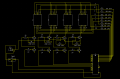
i made 4 inch 4 digit comman anode display with microcontroller. i got the error in decimal point.
when i set low from microcontroller than decimal point is glow. but when i give high than also its glow.
i gave 12V for drive 4 inch seven segment display.

There is 50 ohm Resistor on all A,B,C,D,E,F,G AND DP line.
How can i overcome these problem???
 

WBahn

Joined Mar 31, 2012
30,045
Have you checked the actual voltage on the DP line to make sure that it is what you believe your program is setting it to?

Is this a multiplexed display?

Is it safe to assume that the rest of the segments are all working as expected?

It would be nice to see a schematic.
 

Thread Starter

chirag modesara

Joined Dec 23, 2015
12
yes remaining segment working perfect and this is multiplexed display.

dp line is gives 4 V when i disconnect it from seven segment display.
 
Did you connect a number of single LEDs together to form a segment?

if you did, then 50 ohms is way too low of a resistance for a single LED.

MATH: Guess (12-5*2.1)/50, hypothetically would give about 30 mA per segment of 5 LEDs. Assuming 0V drop for the driver.
 

Deleted member 115935

Joined Dec 31, 1969
0
It might be a complete red mullet

but some displays do not multiples the point, just the other lines,

might be worth looking at if all else fails.
 

Thread Starter

chirag modesara

Joined Dec 23, 2015
12
when i give low voltage from microcontroller to turn it on. then brightness level is slightly decrease as compare to normal position.
when i give high from micro controller than brightness level is higher.
so this is work like opposite logic
 

RichardO

Joined May 4, 2013
2,270
Please post the data sheet for the display. As @andrewmm says the decimal may be only one LED whereas all the other all of the segments are more than one diode in series.
 

Thread Starter

chirag modesara

Joined Dec 23, 2015
12
Hi all,
Thanks for Reply..
i was out of town for 4 days..
Here is my schematic.
There is 5 LED for Each segment in Display and For dp ..its only two LED.
 

Attachments

LesJones

Joined Jan 8, 2017
4,188
Are you sure that the microcontroller outputs can go high enough to turn off the LEDs with 12 volts on the anodes. The 5 in series should work
as they would need the bottom of the chain pulled down to about 2 volts for then to conduct. (So when the micros output was high (I assume +5 volts) the LEDs would not conduct.) As the DP is only 2 LEDs in series the output of the micro would have to go above about + 8 volts before the LEDs would be turned off. I have not seen a microcontroller whose output pin can be taken so high.

Les.
 

Thread Starter

chirag modesara

Joined Dec 23, 2015
12
Thanks For LesJones,

You are think right.
microcontroller cant give greater than 8 volt ouput so its running on.
but is that you have any idea??
how can i give greater than 8 volt on dp line when i want to dp off??
 

LesJones

Joined Jan 8, 2017
4,188
Use driver transistors instead of trying to drive the LEDs directly from the I/O pins. Almost NPN transistor should work. Connect the I/O pin to the base of the transistors with about 1K resistors. You will need to invert the sense of the drive signal to the I/O pins.

Les.
 

Thread Starter

chirag modesara

Joined Dec 23, 2015
12
hi LesJones,

can you tell me which driver Transistor i can you??
Because i used this all BC547,2n222a,bd139,2n3904.
and
Exact connection with emitter,Collector and base.
 

LesJones

Joined Jan 8, 2017
4,188
The emitter will connect to 0 volts. The base to the I/O pin for the relevent segment (Or DP) via about a 1 K resistor. The collector to the LED cathode for the segment via the current limiting resistor. Note you will need to re calculate the current limiting resistor for the decimal point. If you have not yet learned ohms law then this is probably the first step in learning about electricity. (I suspect you would have already have been tought this in school at about the age of 13 so you can re read your text books.) Any of the transistors you listed should work but the BD139 is very much overkill for the job.

Les.
 

EM Fields

Joined Jun 8, 2016
583
@chirag modesara
Can you please post the data sheet for the LEDs you used to build the display or tell us what color they are?
If you can post the data sheet, or a link to it, or a part number, that would help a lot.
 
In post #4, I said this:

Post #4 said:
MATH: Guess (12-5*2.1)/50, hypothetically would give about 30 mA per segment of 5 LEDs. Assuming 0V drop for the driver.p
Modified a bit based on the schematic: =(12-5*2.1-0.6)/50 = 18 mA which is about right.

So, for two LEDs, R <= (12-2*2.1-0.6)/18e-3 = 400 ohms (pick closest standard value)

How did I get those numbers:

12 = The power supply voltage
2 = 2 LEDs
2.1 = An estimate for Vf of a single LED which varies by color
0.6 = An estimate for the Vce (Sat) or about a diode drop
18E-3 or 18 mA = Not a bad estimate for a standard LED; Your multiplexing, so the value can be higher

R<= means pick something close to a standard value.
 

Motanache

Joined Mar 2, 2015
540
Check delays in multiplexing procedure.
To be visible must be on for a rather long time.

If lights for a verry short time, seen as light faded.

Test it with a greater delay after it is ON.
 
Top