Debug Inversion / Center Channel Circuit

Thread Starter

royaaron

Joined Feb 19, 2024
7
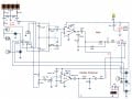
I put together a circuit which is mainly the combination of two circuits I found on websites.
One is for inversion (inverting the left channel, combining it with the right and getting the result).
The other is a center channel.
The designs appeared in several places and seemed to be recognized as correct.
So all I really did was join them and add a bulb and a few switches.
When I connect a small 8 ohm speaker all I get is a hum. And this occurs even without input.
I am using two LM386 ICs which are mounted in sockets (to avoid soldering the IC leads directly).
They're tiny so I had to take care not too short any.
The connections have been tested for continuity (with the leads) and discontinuity (among the socket leads).

Does anyone have any ideas how to go about debugging this?
 

Attachments

Audioguru again

Joined Oct 21, 2019
6,789
Your LM386 amplifiers have a high gain of 200 times due to the capacitors between pin 1 and pin 8.
But the 6.3k and 270 ohm circuit input resistors attenuate the input signals 24.3 times.

The potentiometers and many other parts are between the attenuators and high gain amplifiers. These parts and their wiring are antennas for the 50Hz or 60Hz electrical interference that is all around you causing the hum.

The light bulb connects directly to the 9VDC and might overload it. Then a 9VDC wall-wart will produce 100Hz or 120Hz hum.

All parts should have letters and numbers (example: R12 and C17).
 

MisterBill2

Joined Jan 23, 2018
19,588
With the high gain you are probably picking up the mains frequency. OR you have hum on your power supply voltage. What sort of arrangement is there physically with what you have assembled?? High impedance circuits are certainly subject to hum pickup.
 
Last edited:

Thread Starter

royaaron

Joined Feb 19, 2024
7
Your LM386 amplifiers have a high gain of 200 times due to the capacitors between pin 1 and pin 8.
But the 6.3k and 270 ohm circuit input resistors attenuate the input signals 24.3 times.

The potentiometers and many other parts are between the attenuators and high gain amplifiers. These parts and their wiring are antennas for the 50Hz or 60Hz electrical interference that is all around you causing the hum.

The light bulb connects directly to the 9VDC and might overload it. Then a 9VDC wall-wart will produce 100Hz or 120Hz hum.

All parts should have letters and numbers (example: R12 and C17).
Thank you for your response. I am now using a 9V battery.
 

Audioguru again

Joined Oct 21, 2019
6,789
Since the hum is gone when the circuit is powered from a battery then your power supply produces a small amount of hum that is amplified by the excessive gain of 200 times from the amplifiers.

The datasheet of the LM386 shows a 10uF or more capacitor from pin 7 to ground as a filter to reduce power supply noise.
 

MisterBill2

Joined Jan 23, 2018
19,588
There are two different possibilities relative to the hum delivered by the mains powered supply. The most obvious one is that there is a bit of mains frequency ripple on the supply DC output, caused by inadequate filtering of the rectified voltage. That is often the case, especially when the load is consuming a bit more power than the supply was intended to deliver. (that would be defined as "normal mode" ripple.)
The second potential cause is that there is a bit of "common mode ripple" on the supply output. That would mean that some mains frequency voltage was present on both supply connections, relative to some external "ground" point. That is caused by some form of slight leakage of mains frequency voltage across the supply isolation barrier. That may be due to inadequate isolation either in the project circuit supply, or in the signal source supply.
In either case, changing to battery power would remove the hum voltage problem.
 

Thread Starter

royaaron

Joined Feb 19, 2024
7
Since the hum is gone when the circuit is powered from a battery then your power supply produces a small amount of hum that is amplified by the excessive gain of 200 times from the amplifiers.

The datasheet of the LM386 shows a 10uF or more capacitor from pin 7 to ground as a filter to reduce power supply noise.
I have the 2011 version of the LM386 datasheet. (I'm surprised it's so recent given the age of the IC.) I don't see your reference. In any case, is the 10uF cap electrolytic. If so, NEG side to ground?
 

Audioguru again

Joined Oct 21, 2019
6,789
The high gain amplifiers need the input biasing filter capacitors at pin 7 to ground to reduce power supply hum. Try 10uF then try 100uF.
Edit: The datasheet says, "bypass capacitor" but does not say its "power supply filtering for its input biasing" function that is obvious on its schematic.
The capacitor at pin 7 to ground should be electrolytic with the negative terminal connected to ground.
 
Last edited:

Thread Starter

royaaron

Joined Feb 19, 2024
7
Got it, thank you.
A gain of 20X is really plenty for my purposes. Would removing the 10uF cap between pins 1 and 8 reduce the possibility of overheating the IC?
 

MisterBill2

Joined Jan 23, 2018
19,588
It is not likely that reducing the gain will change the possibility of overheating, unless the amplifier is running at maximum output driving a low impedance load.
 

Audioguru again

Joined Oct 21, 2019
6,789
Got it, thank you.
A gain of 20X is really plenty for my purposes. Would removing the 10uF cap between pins 1 and 8 reduce the possibility of overheating the IC?
If you reduce the 200 times gain to 20 times then you should also reduce the input attenuation.

The datasheet for the LM386 amplifier shows that with your 9V supply and your 8 ohm speaker, the max continuous amplifier heating (dissipation) with a sinewave output is only 0.5W when the output power is from 0.4W to 0.6W. The allowed dissipation is 1.25W, 0.73W or 0.595W depending on which package is used.
If the output signal is a squarewave with lots of clipping then the amplifier heats less.
 
Top