 Facebook
 Google
 GitHub
 Linkedin
Hello,
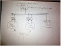
I have a bread board which requires two voltages. The first is 5VDC and the second one is 3.3VDC.
Please view the attachment for a simple schematic.
The problem is that when I adjust my power supply to exactly 5VDC in order to satisfy the 5Volts part of my board, the DC/DC modules shown in attachment deliver 4.27VDC instead of 3.3VDC.
Now I imagine this is because the DC/DC modules have little load on them, but this is really annoying because my components connected to the DC/DC modules really require 3.3VDC or at worst 3.5 MAX!!!
My DC/DC modules are "NKE0503SC". I also realize that the more components I connect to the DC/DC modules the more I get cloeser to the expected DC/DC module voltage of 3.3VDC
My question is, what can one do to temporarily achieve a steady 3.3VDC while building up the board?
I was thinking of putting a 50 ohm resistor between the 3.3VDC rails to temporarily attain the desired approximate 3.3VDC.
all feedback is appreciated!
r
Attachments
-
 79.2 KB Views: 25
")


