DC Motor wiring question

Thread Starter

Hugrafix

Joined May 16, 2017
8
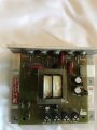
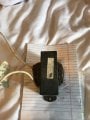
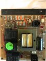
I have been tinkering around with some DC motors and the boards from treadmills to try and bypass the integrated control and add a potentiometer to control motor speed but have been unsuccessful and hoped that I could get some help. My power is 110 on a 20 amp and the power cord has black white and green wires. The DC motor has red, yellow and green wires and attached is a picture of the board. I am adding a fuse and a switch to the black wire on the power wire and have connected the potentiometer to the 3 prong connector. what I am not sure about is where the red and yellow go from the motor and the black and white from the power cord. I thought the black would go to one of the "To Fuse" on the top left of board and the white to the "common" middle top of board. Then I thought the red on the motor would go to "hot" top left of board and the yellow I really had no idea. I have tried all different configurations but just cant seem to get the motor to turn. I tested the motor on a 12v battery and it works. The board lights up when I connect the black and white. Im sure this forum is for for more advanced questions
 

Attachments

MaxHeadRoom

Joined Jul 18, 2013
28,621
There appears to be some of the motor control circuit missing, Just power, I cannot see power semi's for motor speed control?
Is there any on the reverse side of the board?
Max.
 

Thread Starter

Hugrafix

Joined May 16, 2017
8
There appears to be some of the motor control circuit missing, Just power, I cannot see power semi's for motor speed control?
Is there any on the reverse side of the board?
Max.
There is a second board which is what I was trying to bypass and why I added the potentiometer or at least that is what I thought I was supposed to do.
 

Attachments

Kermit2

Joined Feb 5, 2010
4,162
Your pot will burn out if used to directly control the motor. The pot would be used to control a motor controller chip which would handle the large current levels that would damage the pot. itself.

The motor is DC, so it may not like you connecting 120 VAC to it from the white and black wires of the power cord.
 

Thread Starter

Hugrafix

Joined May 16, 2017
8
I also have this to change Ac to D.C. and assumed that connects to the yellow wire from the motor then onto the board somewhere.
 

Attachments

MaxHeadRoom

Joined Jul 18, 2013
28,621
That solves the problem of the missing semi's but I cannot see any control logic on the board, there is normally a couple or more IC's etc.
The latest picture is a motor choke.
Max.
 

Thread Starter

Hugrafix

Joined May 16, 2017
8
That solves the problem of the missing semi's but I cannot see any control logic on the board, there is normally a couple or more IC's etc.
The latest picture is a motor choke.
Max.
Thank you for the response, the only other board is the control board for the treadmill where you set time and speed and all settings. I am attempting to use the motor to build a band saw so I don't want all those controls. Maybe it's time to find another treadmill that might have a different controller
 

MaxHeadRoom

Joined Jul 18, 2013
28,621
The MC-60 MC-80 are popular TM controllers, the down side is they have built in Accel/Decel on them, there is also a feature that requires the pot be at zero before the motor will run, although this can be defeated.
If you want Non-TM types, the KB/Baldor series of similar controllers are out there.
It is also advisable to remove the flywheel, if you want rapid response.
Max.
 

Thread Starter

Hugrafix

Joined May 16, 2017
8
The MC-60 MC-80 are popular TM controllers, the down side is they have built in Accel/Decel on them, there is also a feature that requires the pot be at zero before the motor will run, although this can be defeated.
If you want Non-TM types, the KB/Baldor series of similar controllers are out there.
It is also advisable to remove the flywheel, if you want rapid response.
Max.
I got it working, A1 A2 to motor red and yellow then power from wall went to L1and L2 and my POT to S1 S2 and S3.
 

Attachments

Thread Starter

Hugrafix

Joined May 16, 2017
8
That solves the problem of the missing semi's but I cannot see any control logic on the board, there is normally a couple or more IC's etc.
The latest picture is a motor choke.
Max.
Question for you Max - the power semi you referred to, do I need that? It seems to work either way. I got another treadmill and it has one that just looks like a large green lifesaver with wire wrapped around it, its smaller. Do I just need to put this on the hot wire that goes from the board to the motor? Will either work?
 

MaxHeadRoom

Joined Jul 18, 2013
28,621
That board you show is probably all you need, but I have never seen such a bare-bones board as that, it seems to lack some of the enhanced features usually seen.
The 'Green Life Saver' you mention is a choke that usually goes in one of the motor leads, some have four leads for a common-mode choke configuration.
If you have it, you may as well use it.
Max.
 

Thread Starter

Hugrafix

Joined May 16, 2017
8
That board you show is probably all you need, but I have never seen such a bare-bones board as that, it seems to lack some of the enhanced features usually seen.
The 'Green Life Saver' you mention is a choke that usually goes in one of the motor leads, some have four leads for a common-mode choke configuration.
If you have it, you may as well use it.
Max.
Thank you Max!
 
Top