DC motor control using 555 timer

Thread Starter

sagivbh

Joined Jan 15, 2018
28
Hi,
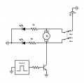
I wish to build a DC motor controller. I have a window motor from my father's old chevrolet car. I found online a circuit that generate 12 volts duty cycle square wave to transistor base.
First question: when I generate the square wave, only the duty cycle is responsible for the RMS voltage?
Second question: I wish to add two led diodes for the polarity of the motor. How can I do it properly?
Last question: I want to add a on off toggle switch. The proper way to turn off the circuit is to first take pin 4 to the ground, and than turn off the power suppley?
Thanks!
 

Attachments

Norfindel

Joined Mar 6, 2008
326
Check the current requirements of the motor, to see if the BD139 is enough to switch something like that.

1- The lowest the duty cycle, the lowest the rms value, the slowest the motor will move (maybe even stop).
2- The simplest way, would be connecting a resistor to the motor + terminal, in series with one led, and the cathode of the led to gnd. So, when the switch is in the up position, the motor + is actually connected to Vm, and the led will light. The value of the resistor depends on the value of Vm. As it's a car's window motor, i assume that Vm is 12v, so (12v - 2v) / 10 mA = 1000 ohms. You can use a red, green, or yellow led, they have roughly 2v of drop. If you want a 2nd led, you can do exactly the same again, but this time, the resistor will be attached to the motor - terminal.
3- An on/off switch is a switch that cuts the power off. For example: if you have a 12v supply, instead of conecting the supply + terminal to the circuit directly, you connect it to one terminal of the on/off switch, and the other terminal of the switch will power the circuit. The supply's - terminal is directly connected to the circuit's - terminal (identified as gnd in the schematic).
 

Thread Starter

sagivbh

Joined Jan 15, 2018
28
Check the current requirements of the motor, to see if the BD139 is enough to switch something like that.

1- The lowest the duty cycle, the lowest the rms value, the slowest the motor will move (maybe even stop).
2- The simplest way, would be connecting a resistor to the motor + terminal, in series with one led, and the cathode of the led to gnd. So, when the switch is in the up position, the motor + is actually connected to Vm, and the led will light. The value of the resistor depends on the value of Vm. As it's a car's window motor, i assume that Vm is 12v, so (12v - 2v) / 10 mA = 1000 ohms. You can use a red, green, or yellow led, they have roughly 2v of drop. If you want a 2nd led, you can do exactly the same again, but this time, the resistor will be attached to the motor - terminal.
3- An on/off switch is a switch that cuts the power off. For example: if you have a 12v supply, instead of conecting the supply + terminal to the circuit directly, you connect it to one terminal of the on/off switch, and the other terminal of the switch will power the circuit. The supply's - terminal is directly connected to the circuit's - terminal (identified as gnd in the schematic).
Thank you for your answer and help!
I draw the new schematics with the diodes. I think i didnt understand well, beacuse i see that i will light the two diodes the way in the picture. is that the right way?
Thank you agian!
 

Attachments

dendad

Joined Feb 20, 2016
4,451
I use an RG LED, or 2 separate LEDs back to back, and one resistor.
RG-MotorLED.jpg
In fact, I've made up a number of test leads with a dual LED and a 2K2 resistor all in heat shrink. They are very handy as test loads or indicators. Wire them up with one red wire and one green wire, with the colour of the LED that lights indicating which wire is the positive.
Like Kingbright L-937EGW ( https://au.rs-online.com/web/p/visible-leds/2285641/ )
Or you can of course just use a red and a green LED.
 

Thread Starter

sagivbh

Joined Jan 15, 2018
28
The DPDT has a centre off to ensure you go to an off position first before going from CW to CCW immediately.
Max.
Oh! yes of course, I understand know. Thanks for the tip!

I use an RG LED, or 2 separate LEDs back to back, and one resistor.
View attachment 166654
In fact, I've made up a number of test leads with a dual LED and a 2K2 resistor all in heat shrink. They are very handy as test loads or indicators. Wire them up with one red wire and one green wire, with the colour of the LED that lights indicating which wire is the positive.
Like Kingbright L-937EGW ( https://au.rs-online.com/web/p/visible-leds/2285641/ )
Or you can of course just use a red and a green LED.
Thanks for answering! This back to back diodes are going to take voltage from the motor?
 
Last edited:

Norfindel

Joined Mar 6, 2008
326
Im sorry I draw the last scematics too fast.
Here is the new picture.

I didnt get your hint. Im sorry.
Yes, that's what i proposed. But i realized that there's a chance that with the transistor off, enough current would pass thru the motor's windings to lit both leds, so you need to test it to be sure.
The two leds back to back won't have that issue, but the leds will be dimmed by the PWM.
 

Thread Starter

sagivbh

Joined Jan 15, 2018
28
Yes, that's what i proposed. But i realized that there's a chance that with the transistor off, enough current would pass thru the motor's windings to lit both leds, so you need to test it to be sure.
The two leds back to back won't have that issue, but the leds will be dimmed by the PWM.
Oh they will dim, I forgot about the square wave. Thanks a lot for helping, I really appreciate it!
 

Norfindel

Joined Mar 6, 2008
326
You're welcome.
Another way, would be to use a switch with an additional pole, then you use that pole to send 12v to two different leds, and conect the cathodes together, and then they go to a 1k resistor to gnd. That won't have any issues that i can think of, and won't flicker, and is simple.
 

Thread Starter

sagivbh

Joined Jan 15, 2018
28
You're welcome.
Another way, would be to use a switch with an additional pole, then you use that pole to send 12v to two different leds, and conect the cathodes together, and then they go to a 1k resistor to gnd. That won't have any issues that i can think of, and won't flicker, and is simple.
Thanks! I will try that.
 
Top