DC excitation to car alternator

MaxHeadRoom

Joined Jul 18, 2013
28,702
Seems this thread has taken on a treatise on the various construction methods of alternator regulators, all the OP needed was an answer to the question "can i use a 12v supply to excite alternator instead of a battery?"
This could and was answered in a couple of posts.
In some cases there is enough residual in the rotor that with a about half a dozen components a self regulator can be built with no external source required.
Max.
 

MaxHeadRoom

Joined Jul 18, 2013
28,702
Hi Asralan-Zia,

Do hope the diagram makes things clearer.
Regards,

Nandu.
That is a generic diagram, many alternators, especially the old popular GM such as the CS 4 pin connector series had one brush at ground potential, the other switched with the internal electronic regulator.
This has to be known or in some cases modified if feeding the field with a separate supply.
Max.
 

MikeML

Joined Oct 2, 2009
5,444
Besides, Nandu's diagram is obsolete. The extra diode trio for field excitation, and the back-feed idiot lamp hasn't been used in any car made in the US since 1970. Nowadays, the field excitation comes from the car battery with only six diodes in the diode stack.
 

tcmtech

Joined Nov 4, 2013
2,867
Besides, Nandu's diagram is obsolete. The extra diode trio for field excitation, and the back-feed idiot lamp hasn't been used in any car made in the US since 1970. Nowadays, the field excitation comes from the car battery with only six diodes in the diode stack.
Not true. I've had many newer 2000+ model automotive and other types of alternators apart and most everyone still has the diode bridge in them. Many have it built into the internal regulator assy but they are infact still very much a part of the unit.

As for the alternator light not being ins US vehicles since 1970 I call BS. Ford and Chevy still had that light in many of their base models well into the mid 90's if not later.

I'm not sure where you get your alternator facts and general info from but whenever you post most anything about alternators I cringe just before reading it. :(
 

MikeML

Joined Oct 2, 2009
5,444
From personal experience and observations I can say that years ago both DC generators and AC alternators used the same type of electromagnetic buzzing solenoid designs to control their voltage output. ....
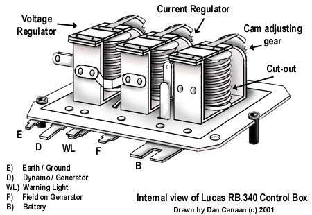
You better go look some more. DC generator controllers are different than Alternator controllers. Even in the day of vibrating relay contact controllers (and I have repaired both) , generator controllers have three relays , while alternator controllers have only two relays.

The third relay in the generator controller is the current cutout (bobbin wound with heavy wire, used as a current sensor) which pulls-in if the output current rating of the generator is exceeded.


There are only two relays in the alternator controller; one is the cutout (to prevent battery discharge into the field/regulator when the Ignition switch is off), and the other is the voltage cut-out (voltage regulator). How do I know this? I still have the vibrating-point electro-mechanical Prestolite regulator I pulled off my 1967 Cessna here in my junk box. I can take a photo, if you like...

As for current limiting to protect things unfortunately the majority of the common automotive alternators will burn themselves up just the same as a DC generator without its current limiting regulation circuit in place will if they are overloaded for too long.
My turn to call BS! I have had alternators wear out brushes, and had to replace a rectifier, but have never had one "burn up" where the stator, or rotor windings had to be rewound..., can't say the same for a generator. There is no active current-limiting (except fuseable links) in millions of alternator equipped cars, and their reliability is excellent.

At a constant RPM and constant field winding power both systems behave identically. Output voltage and current limits behave the same. Low current draw results high output voltage. High current draw results in lower output voltage and overloading eventually results in smoke. :p
BS again! A spun-up open-circuited generator with 12V connected to its field is doing good to produce 40V. An alternator under similar conditions will make an open-circuit voltage of >120V. An overload generator will smoke if the current-cutout is disabled or misadjusted. An alternator will not because it is intrinsically current-limited by design due to magnetic saturation. An alternator rated for 60A @ 12V will not put out more than ~65A @ 0V.
At a fixed input RPM's and fixed field excitation levels both behave as voltage sources and neither limits their current until some internal effect like winding resistance or impedance comes into play just like any voltage source works.
BS again! A generator is a voltage source, and therefore is not current limited and needs to be externally current limited as in the controller cited above. An alternator is quite different. It is specified to deliver a rated current into 12V. It puts almost the same current into a short as it does into a battery.
 
Last edited:

MikeML

Joined Oct 2, 2009
5,444
Not true. I've had many newer 2000+ model automotive and other types of alternators apart and most everyone still has the diode bridge in them. Many have it built into the internal regulator assy but they are infact still very much a part of the unit.
Then you will have to explain why I have an externally-regulated Prestolite 60A Alternator here that was originally used in a mid-1960s Ford sedan that has only 6 rectifiers in the stack. It does not have the three extra rectifiers (diode trio) to supply the field excitation as shown in Nandu's schematic. The excitation comes from the battery via the cutout relay inside the regulator. This alternator has only three external connections: the case which is gnd, the Bat stud (+ output of the rectifier stack), and Field. One of the two Field brushes is grounded, so this alternator needs a current-sourcing regulator.

I have repaired some Chrysler charging systems (from the 1970's era) that also have only six diodes; they require a current-sinking regulator.

No three extra diodes in Nippon-Denso (Toyota, Subaru) alternators (internally regulated, but they sense the system battery voltage via a wire controlled by the ignition switch. No Idiot light; just a voltmeter

The only alternators that I have seen recently that have the three extra diodes are the one-wire, internally-regulated, self-excited ones that are much loved by the hot-rod crowd. Again, no Idiot light.

I have a boat with a Paris-Rohne (French pos) that does have the extra diodes, but they are not used by the regulator or connected to the Field circuit. They likely had a bunch of old rectifier assemblies that they had to use up. No Idiot light; just a voltmeter

As for the alternator light not being ins US vehicles since 1970 I call BS. Ford and Chevy still had that light in many of their base models well into the mid 90's if not later.
Some newer cars have an illuminated "not charging" lamp or LED instead of a voltmeter, but it is not a required part of the charging system like it was in British cars, Volvos and a few Russian knockoffs. In the system shown by Nandu, if the lamp burns out, the alternator will not "bootstrap" itself.
I'm not sure where you get your alternator facts and general info from but whenever you post most anything about alternators I cringe just before reading it.
Who you gonna believe, an engineer or a shade-tree mechanic?
 
Last edited:

tcmtech

Joined Nov 4, 2013
2,867
You better go look some more. DC generator controllers are different than Alternator controllers. Even in the day of vibrating relay contact controllers (and I have repaired both) , generator controllers have three relays , while alternator controllers have only two relays.
I never said they were exactly the same. what I said was, From personal experience and observations I can say that years ago both DC generators and AC alternators used the same type of electromagnetic buzzing solenoid designs to control their voltage output. Given that I know that the two and three relay type regulators can control a alternator being the high current cutout relay that normally disconnects the generator from the electrical system is not needed due to the alternator having diodes.


Who you gonna believe, an engineer or a shade-tree mechanic?
Depends on their personal track record and factual accuracy of their opinions and or actual supposed knowledge base just like everyone else here. Some have it together and others just think they do because they have a title by their name. :rolleyes:

As with many here I have known and worked with people in both categories who both ruled their respective knowledge bases or were bumbling idiots who were too dumb to even realize how little they knew about what they worked on for a living.

Unfortunately I have to say I have met more engineers who assumed that since they have a tile or know a bit of something about one particular design or brand that every other design and brand were the same.

How many diodes are in a alternator? Well I have seen them with anywhere from 6 to 12 on the main bridge and any were from zero to 6 on the regulator circuits.

Relating to alternator indicator lights in vehicles if it lights up to tell me the alternator is not working that's an alternator light to me. Who made it and when or what continent it can be found on is irrelevant to me. A indicator that lights up when the alternator is not spinning/working is a alternator light to me. ;)
 
Last edited:

tcmtech

Joined Nov 4, 2013
2,867
Since I have some time today. :p

I have had alternators wear out brushes, and had to replace a rectifier, but have never had one "burn up" where the stator, or rotor windings had to be rewound..., can't say the same for a generator. There is no active current-limiting (except fuseable links) in millions of alternator equipped cars, and their reliability is excellent.
I suggest you do a far more expanded and detailed analysis of the alternators in use today. The older designs were harder to burn up but were by no means bulletproof. I've replaced dozens of alternators over the years and I can assure you that very few are burn out proof. In fact other than the ones specifically designed for high continuous duty applications most automotive type alternators will only last a few tens of minutes or less when taxed to their maximum rated outputs.
To be honest if you talk to the service department people at most any auto dealership they will tell you that with the newer vehicles jump starting another vehicle is not recommended just because the high current demand can easily cook their alternators. :(

A spun-up open-circuited generator with 12V connected to its field is doing good to produce 40V. An alternator under similar conditions will make an open-circuit voltage of >120V. An overload generator will smoke if the current-cutout is disabled or misadjusted. An alternator will not because it is intrinsically current-limited by design due to magnetic saturation. An alternator rated for 60A @ 12V will not put out more than ~65A @ 0V.
Open circuit voltage for both is highly dependant on their input RPM's plus the magnetic properties of their metallic core components.
The old two pole DC generators would go into core saturation at far lower levels than the newer types of laminated steels that are used in automotive alternator designs do which in turn has substantial effects on the maximum magnetic field strengths that each dsigns field coil assy can produce and transfer given equal rotor face speeds which result and account for the drastically different peak open circuit voltages given identical mechanical speed inputs.

As for maximum rated current again that will depend on the metallic core designs plus other factors including how the manufacturer chose to rate their unit.
I have tested many Motorcraft alternators and as you say they were rated for ~63 amps and could barely reach that in a dead short.:(
But I also have worked with many other designs like the Delco SI series of which any decent version of them typically will put out the rated current while maintaining at least 12 volts or more with the capacity to go a fair amount past that in a dead short.

The last commercial application alternator I put on one of our tractors was a 12 volt Delco 22SI rated at ~135 amps. The actual as tested specs sheet that came with it shows it can easily put out upwards of 190 amps while holding 12 volts or higher but it's still only rated for 135 amps at 12 volts or better. :cool:

Then you will have to explain why I have an externally-regulated Prestolite 60A Alternator here that was originally used in a mid-1960s Ford sedan that has only 6 rectifiers in the stack. It does not have the three extra rectifiers (diode trio) to supply the field excitation as shown in Nandu's schematic. The excitation comes from the battery via the cutout relay inside the regulator. This alternator has only three external connections: the case which is gnd, the Bat stud (+ output of the rectifier stack), and Field. One of the two Field brushes is grounded, so this alternator needs a current-sourcing regulator.
I would say that it's because you have a Prestolite 60 amp externally regulated alternator that uses a current sourcing regulator system which is just one of dozens of different alternator designs and not the least bit of an all encompassing representation of all alternator designs in use today. :rolleyes:

I have a good collection of both old alternators and DC generators and some use current sourcing while others use current sinking regulator systems which to me means that neither is a fair and only true representation of all types of either devices design and possible control.
Many manufacturers used one style for one application and then they used another style in a different application.
I have a number of old 6 volt Delco Remy and Motorola generators that look identical but some use a current sinking field control and the others use current sourcing field control. Either way internally they are pretty easy to switch over.

A generator is a voltage source, and therefore is not current limited and needs to be externally current limited as in the controller cited above. An alternator is quite different. It is specified to deliver a rated current into 12V. It puts almost the same current into a short as it does into a battery.
I would say that argument is largely a matter of semantics. As far as I know all voltage sources are also current sources and all current sources are also voltage sources being you can't have one without the other. :rolleyes:
As for how that relates to DC generators Vs alternators I say they are both voltage sources until they reach the current limits that their internal physical components will allow just as any bench top voltage or current source will which is why they have output rating limits on them.
When they are used within their designed parameters they work exactly like they are supposed to but when you push them beyond that they will obviously act/react in undesired ways like either shutting down of letting their smoke out just like a generator or alternator will if pushed beyond its rated working capacities.
A DC generator will no longer work like a voltage source once the current demands reach a point where the combination of magnetic field flux saturation limits and winding resistance limits start to become the primary limiters in the circuits operation. Same with an alternator.

Personally I see no difference in the classification of either just because one is designed physically different and has different physical limits due to its design.
With proper design a DC generator and a alternator could be constructed that have identical open circuit voltages at the exact same RPM's and also have exactly the same current output/voltage output slope curves as well which to me then does not mean that one or the other is to be classified different because of its physical layout when both units mechanical to electrical conversion values are identical.

I have repaired some Chrysler charging systems (from the 1970's era) that also have only six diodes; they require a current-sinking regulator.
Yes that is the standard design that Chrysler used back then but again no where near an accurate representation of all alternator designs ever made. At that time Ford used a different design and GM used another design as well as did countless other auto and equipment manufactures.
I am familiar with each of their designs from that era along with many of their more modern versions that are in current production today plus am more than sufficiently aware of their wiring and control system setups to be able to refit one brands units into another brands vehicles such as transplanting Delco SI series units into Ford and Chrysler vehicles or vice versa depending on the need.

The only alternators that I have seen recently that have the three extra diodes are the one-wire, internally-regulated, self-excited ones that are much loved by the hot-rod crowd. Again, no Idiot light.
Yes and as stated before they are just one of many designs. I have a bunch of the new style one wire low excitation speed regulators that go into the Delco SI alternators that don't use any diode trio to work. That doesn't mean they are a representation of all alternators everywhere.

As I see it a DC generator and an alternator are both the same types of devices. The only difference is the design of a alternator allows for it to convert far more mechanical energy into electrical energy in a similarly sized physical package.
When working as designed and intended within their designed limits they are forthe most part identical devices.
What they do when ran outside their designed applications due to modification or damage/malfunction is totally irrelevant. ;)
 
Last edited:

allaidept

Joined Mar 5, 2017
17
Hello.
I saw someone used a car alternator in a stationary bike energy producing project, charging a 12V battery using human body power.
He used a 20 W 8 Ohm resistor in series with the excitation coil.
Any clue why he did this?
Thanks.
 

allaidept

Joined Mar 5, 2017
17
Hello,
So, practically, I need to charge a battery using no more than 1Ah using a car alternator mounted on an fitness bicycle.
It is hard to achieve 1000 rpm.
What do you propose to change in system? I do not need lots of charging Amps, I need just low rpm.
Thanks.
 
Seems this thread has taken on a treatise on the various construction methods of alternator regulators, all the OP needed was an answer to the question "can i use a 12v supply to excite alternator instead of a battery?"
This could and was answered in a couple of posts.
In some cases there is enough residual in the rotor that with a about half a dozen components a self regulator can be built with no external source required.
Max.

i want to know the automotive alternator is self excited or separately excited?
 

shortbus

Joined Sep 30, 2009
10,045
thanks for your information ,,
if any alternator available with self excitation for automotive application.?
Not that I ever heard of. The rotor has an electromagnet in it, this is to allow the alternator to be easily regulated to fit the needs of the vehicle, by varying the voltage to the electromagnet. If it was a permanent magnet the regulation would need to be done by shunting to ground, this is how most motorcycle alternators do it. They have a permanent magnet rotor in them.
 

MaxHeadRoom

Joined Jul 18, 2013
28,702
thanks for your information ,,
if any alternator available with self excitation for automotive application.?
Haven't come across one, I'm not sure why an auto Alternator does not retain residual in the field enabling self excitation as the most common DC generator do, even Edison's original did that!.
Max.
 

shortbus

Joined Sep 30, 2009
10,045
Haven't come across one, I'm not sure why an auto Alternator does not retain residual in the field enabling self excitation as the most common DC generator do, even Edison's original did that!.
Max.
Think it might have something to do with the type of steel in the claws. Or maybe it could be they get demagnetized as they a coming to a stop, with the induction voltage still in the stator coils and them spinning. But like you I've never seen one that still had a residual magnetic field in it.
 

cork_ie

Joined Oct 8, 2011
428
This is an old thread and a lot of different opinions.I was tempted to reply many times but never did. I have been repairing alternators since 1976 and did several every day until about 10 years ago,when the Chinese built new units cheaper, than I could buy parts and recondition used ones.I still do a few but far less.
My take is as follows:
Faraday's laws , which everyone accepts, state that the induced emf in a wire of length (l ) moving at a speed (v) through a magnetic field (B) is proportional to Blv.
In an a car alternator the "length" of the stator coil or the armature winding in a DC dynamo (generator) is fixed
The speed is variable by a factor of about 6 and cannot be easily controlled, except by a very complex governor. Thus the only thing that can be easily controlled is the strength of the magnetic field. In both DC dynamos and alternators, this is how the charging is controlled in practice. As previously mentioned in several posts , the voltage regulators in both instances function more or less the same way. Voltage is controlled by delivering an average current to the field winding, sufficient to maintain a field strength that controls the charging voltage to the desired range of about 13.8V-14.5V
The principal differences between an alternator and a DC dynamo (Generator) are:
(1) The current through the brushes in an alternator only supplies the field current, and is typically only about 3A. It is fed through slip rings, thus sparking is very slight with good brush & slip ring life. In some cases the field current can be fed by induction and the brushes eliminated .
In a DC dynamo, the full output current flows through the brushes , furthermore the dynamo armature has a commutator, with much more sparking and heat at the brushes and much shorter brush life. Output current is limited for a given size and peak armature speeds need to be lower.
(2) In a DC dynamo, a voltage sensitive relay known as a "cut out" is required to prevent the battery draining back into the armature when battery voltage is above armature output voltage. An alternator does not require this feature as the diodes in the rectifier do the same job.
3) Because AC current is being induced in the stator and the stator core is highly inductive, there is natural current limiting in the core due to the opposing emf every time the current direction changes in the stator, as each pole pair of the rotor passes a particular winding during rotation. In a dynamo the inductance in the brush connected winding of the armature is much less and there is no direct conductance path for reverse currents to flow; once that particular winding has moved and is no longer connected to the brushes, any induced current has to dissipate through the full armature winding. Thus we generally see some form of current regulation in the output of a DC dynamo with any significant charge rate above about 12A. While not strictly necessary, armature and brush life will suffer without it.
4) In both cases the current output is a function of the difference between the voltage at the alternator/dynamo output and the battery terminals divided by the resistance of the circuit & internal resistance of the battery, up to the current output limit of the machine.
5) Standard lead acid batteries at normal temperatures will generally perform well at a charging voltage somewhere in the range 14-14.5 Volts . Batteries are damaged by high voltage, as the charging current rapidly tapers off as the battery voltage rises to equalise with the alternator output voltage.

Finally to answer the original question.
Dynamos generally hold sufficient residual magnetism in the field coil pole shoes to allow the armature to charge at about 2.2V without exciting the field. As the "cut out" is still open this voltage is fed directly back into the field windings and rapid excitation occurs at a cut in speed which is generally about 1,000 engine RPMs.
The alternator's stator is permanently connected to the rectifier and on to the vehicle battery and system. The rotor is made of a softer less magnetic iron to facilitate rapid fluctuations of the magnetic field and thus any residual field is much weaker. In practice an alternator will eventually self excite but it may be at about 4,000 RPM and the common method of excitation was to feed a small current from the ignition switch through a small 5Watt bulb , which doubles as a charge warning light. Thus some source of power is required to initially excite MOST alternators. The most important thing is that alternator outputs must always be connected to a battery as damage to the rectifier and electronic regulators are otherwise more or less inevitable. So whatever way you wish to excite your alternator you must always have a battery to act as a load connected across the output.
CAVEAT: All the previous information is (was?) for ordinary bog standard vehicle charging systems. As with everything else technology has changed completely in the last 10 years and many newer alternators are fitted with programmable "regulators" which monitor everything from battery temperature, to electrical load, engine overrun, alternator internal temp, etc. etc.These "Smart" charging systems charge based on an algorithm which determines best charge rate and battery voltage at a particular moment for optimal charging and fuel economy etc.
Hope this answer goes in some way to answering the original post and subsequent "arguments"
 

MarinJim

Joined Oct 23, 2020
2
An alternator is not like a DC generator. The battery is what keeps the voltage near ~14V. Saying you can control the output voltage of an alternator by controlling the field is like saying you can control the current through an LED by controlling the voltage across it, or like saying you can control the voltage at the collector of a transistor by controlling the base voltage...

What controls the voltage out an alternator is the car's battery being in parallel with the output. Removing the battery while the engine is running almost guarantees the destruction of every item of electronics in the car because without the battery, the voltage can and will shoot up to >100V. Look up "Load Dump".

Read this explanation of what is going on inside the typical automotive charging system.
Your "explanation" is a pretty good example of circular reasoning. You model the alternator as a current source, and than assert it shows that an alternator is a current source.
Unfortunately, you model is not an accurate model of reality.
At any given rotor excitation current, and at a fixed RPM, the alternator is a fixed voltage source of modest impedance (a fraction of an ohm.)
 

MisterBill2

Joined Jan 23, 2018
18,600
An alternator is not like a DC generator. The battery is what keeps the voltage near ~14V. Saying you can control the output voltage of an alternator by controlling the field is like saying you can control the current through an LED by controlling the voltage across it, or like saying you can control the voltage at the collector of a transistor by controlling the base voltage...

What controls the voltage out an alternator is the car's battery being in parallel with the output. Removing the battery while the engine is running almost guarantees the destruction of every item of electronics in the car because without the battery, the voltage can and will shoot up to >100V. Look up "Load Dump".

Read this explanation of what is going on inside the typical automotive charging system.
ABSOLUTELY I can control the current through an LED by controlling the voltage applied to it. Of course the control is very non-linear, and also temperature dependent, but I can control it.
For an alternator NOT connected to a battery, changing the field voltage changes the output voltage quite well. Of course when a constant voltage battery is connected the voltage control also changes the current. And the charging current certainly does affect the battery voltage some.
 
Top