 Facebook
 Google
 GitHub
 Linkedin
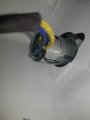
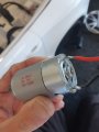
Hi,The part number will allways be on the top. The manufacturer has probably sanded it off to make reverse engineering more difficult. I have noticed that in post #10 you say that the voltage on the motor termonals does not ramp up as the motor speeds up. (If I understand your wording correctly.) I (And I suspect the others.) assume that that the motors are simple permament magnet brushed motors. Is this assumption correct ? Are there any other thin wires going to the motor units. The reason for this question is that the speed control could be done in the motor assemblies. (This is not very likely.) can you try connecting a normal 12 volt filament bulb (About 20 watts. Such as a car stop light bulb.) in place of one of the motors. Does this come on straight away at full brightness or does it take the 20 seconds or so to reach full brightness ? (This question is just in case your multimeter was reading the peak voltage of a PWM (Pulse width modulation. Google it if you do not understand PWM. ) signal. I have never seen a multimeter that would give false readings like this but it is the only way I can see why it would read 12 volts while the motor speed was ramping up. If you connect one of the motors directly to 12 volts does it reach full speed quickly ?
Les.
Good idea about the light bulb. Put one right across the motor. That should allow 'seeing' the ramp speed.

")


