Dc circuit with slow start function

Thread Starter

AdamSkachill

Joined Aug 8, 2018
13
Hey guys,
So I'm completely new to electronics and don't understand the abriviations etc so bare with me
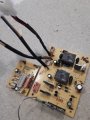
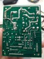
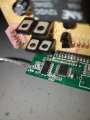
This board is out of a kids ride on toy, the slow start function lags so bad and takes a very long time to build rpm at the motor. So I either want to remove the function all together or make it not so aggrisive. The toy also has 2.4ghz parent remote which I want to try keep to. Can anyone tell me what components on the board would be used to create the soft start?
 

Attachments

Thread Starter

AdamSkachill

Joined Aug 8, 2018
13
Sorry I worded that badly... a slow start would still be okay as long as the motor reached full rpm in say 3 seconds instead of the 20 seconds it takes at the moment. I'm aware these are Chinese junk. But something cool to fiddle with... I have multimeter etc and can remove and solder components to the board. Thanks for the quick reply!
 

MrAl

Joined Jun 17, 2014
11,457
Hi,

Unless you find someone familiar with this specific controller you would have to supply a schematic.
It could be as simple as a change in one of the capacitors, or it may not even be possible.
 

crutschow

Joined Mar 14, 2008
34,408
About the only way I see to possibly determine what's causing the startup delay is to monitor the voltage across each of the capacitors while it is starting to see if one of them shows a voltage change during the startup.
(The capacitors are the big round aluminum and oval greenish components.)
Then reducing the size of that capacitor may help.
 

LesJones

Joined Jan 8, 2017
4,188
It is possible that the delay is done in software. The board plugged into the top of the board that contains two relays could contain a microcontroller. I clear picture of that board so the part numbers of the ICs can be read may be helpful. Has the toy always behaved in this way or was the delay originally shorter ?

Les.
 

AnalogKid

Joined Aug 1, 2013
11,036
1. Is the motor reversible?

2. Please identify the function of each of the wire pairs.

3. What connects to the pink header in the upper right corner?

Near the pink connector are parts that look like an H-bridge motor driver. This sorta makes sense if the motor is reversible. As above, a microcontroller on the RF board might be controlling motor speed through PWM (pulse-width modulation), a technique for running a DC motor at variable speeds without generating a lot of excess heat in the driver electronic components. Not trying to be harsh, but if this is the case, you're sunk.

ak
 

Thread Starter

AdamSkachill

Joined Aug 8, 2018
13
1. Is the motor reversible?
Yes, via a little switch which swaps polarity

2. Please identify the function of each of the wire pairs.
Red/black is battery In, 1 set of yellow/blue does the steering motor via the remote and the other pair is output to the drive motors at the wheels

3. What connects to the pink header in the upper right corner?

Near the pink connector are parts that look like an H-bridge motor driver. This sorta makes sense if the motor is reversible. As above, a microcontroller on the RF board might be controlling motor speed through PWM (pulse-width modulation), a technique for running a DC motor at variable speeds without generating a lot of excess heat in the driver electronic components. Not trying to be harsh, but if this is the case, you're sunk. Hope not

ak
 

Thread Starter

AdamSkachill

Joined Aug 8, 2018
13
Hi,

Unless you find someone familiar with this specific controller you would have to supply a schematic.
It could be as simple as a change in one of the capacitors, or it may not even be possible.
And that's why I thought I'd ask the guys with a whole lot more insight than myself... and I get to learn some new things by playing and testing stuff on the board
 

Thread Starter

AdamSkachill

Joined Aug 8, 2018
13
The pink connector is like a ribbon cable that goes from one board to the other... I also think it's a current restriction rather than voltage if that makes sense as there is 12v at the motors as soon as the rocker switch on the pedal is pressed.

Thanks for all the input so far guys!!!
 

LesJones

Joined Jan 8, 2017
4,188
The only data I can find on the 8002A IC is for a low voltage bridged audio amplifier IC. This is a link to the data sheet . I don't see see that this can be related to the motor control. The IC I was most interested in is the 20 pin device shown on the picture in post #13.

Les.
 

MrAl

Joined Jun 17, 2014
11,457
It is possible that the delay is done in software. The board plugged into the top of the board that contains two relays could contain a microcontroller. I clear picture of that board so the part numbers of the ICs can be read may be helpful. Has the toy always behaved in this way or was the delay originally shorter ?

Les.
Hi,

That's what i was afraid of too that's why i mentioned that it may not be possible to alter the delay.
Unfortunately we still dont know the circuit and the parts in that circuit.
It's probably easier to make the delay longer than it is to make it shorter too :)
 

Thread Starter

AdamSkachill

Joined Aug 8, 2018
13
The only data I can find on the 8002A IC is for a low voltage bridged audio amplifier IC. This is a link to the data sheet . I don't see see that this can be related to the motor control. The IC I was most interested in is the 20 pin device shown on the picture in post #13.

Les.
Thanks for that info Les....
The bigger IC has no marks letters or numbers on it :/ unless they are on the under side?
 

LesJones

Joined Jan 8, 2017
4,188
The part number will allways be on the top. The manufacturer has probably sanded it off to make reverse engineering more difficult. I have noticed that in post #10 you say that the voltage on the motor termonals does not ramp up as the motor speeds up. (If I understand your wording correctly.) I (And I suspect the others.) assume that that the motors are simple permament magnet brushed motors. Is this assumption correct ? Are there any other thin wires going to the motor units. The reason for this question is that the speed control could be done in the motor assemblies. (This is not very likely.) can you try connecting a normal 12 volt filament bulb (About 20 watts. Such as a car stop light bulb.) in place of one of the motors. Does this come on straight away at full brightness or does it take the 20 seconds or so to reach full brightness ? (This question is just in case your multimeter was reading the peak voltage of a PWM (Pulse width modulation. Google it if you do not understand PWM. ) signal. I have never seen a multimeter that would give false readings like this but it is the only way I can see why it would read 12 volts while the motor speed was ramping up. If you connect one of the motors directly to 12 volts does it reach full speed quickly ?

Les.
 
Top