 Facebook
 Google
 GitHub
 Linkedin
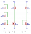
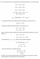
Hi, I have to find Vo and I did it, but I can not prove that M4 and M5 are in saturation(active mode), this is what I did


Attachments
-
 162.9 KB Views: 5
 -
 907.1 KB Views: 3
Last edited:


