Facebook
 Google
 GitHub
 Linkedin

The idea of this project was to build a current source that drives 3 high powered LEDs represented in this circuit by the resistances R9-R11. I realize LEDs are not linear but this is there maximum resistance resulting in the hardest condition for the current source. My problem is that X1 seems to be oscillating with added oscillation when the LEDs are turned off. I have come to this conclusion that X1 oscillates by itself because grounding the bottom of the 5Ω resistor still results in circuit oscillation. I was using a 741CN originally, but than changed to a 301CN and this actually seemed to reduce the problem. What really helped reduced the problem farther was adding capacitors on the positive and negative rails of my power supply (more/less the negative rail had the much larger effect). Ideally I need an op-amp that can handle 20V rails so I bought a couple of UA748INs, but they seem to oscillate REALLY badly(if anyone knows a fix for it you would be saving me some money! =P). After reducing the problem a lot I ran into the problem that when my switches (M2,M4,M5) were on (LEDs off) the oscillation became worse. My first guess has been that they are adding a capacitive load to the op amp, but you would think that Q1 would help stop this effect. I am stuck on this problem with no real solution or ideas on how to fix it or if my thoughts are even correct. The oscillation is roughly a volt(peak-peak).
So what am I am looking for is a fix for the op-amps i bought and/or just a new part that performs like the 301CN and can handle +20/-20V, and help on how to fix the oscillation when the LEDs are off. All help is appreciated! A picture of the circuit is shown below.
NOTE: I know the switch design is not ideal but with the project specifications the way they are I had no better choices.
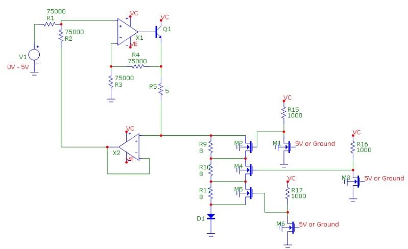
So what am I am looking for is a fix for the op-amps i bought and/or just a new part that performs like the 301CN and can handle +20/-20V, and help on how to fix the oscillation when the LEDs are off. All help is appreciated! A picture of the circuit is shown below.
NOTE: I know the switch design is not ideal but with the project specifications the way they are I had no better choices.