Facebook
 Google
 GitHub
 Linkedin
Hi,
I am wondering if somebody could help with a current limiting circuit I am trying to implement.
What I have is a small 12v dc motor with gearbox.
This will be operating a mechanical valve.
As the valve reaches the end of its travel the motor will load and begin to stall.
This valve will be operated at most once a day.
The motor/gearbox does not have enough torque to cause damage to the valve, just enough to close it tightly. Also the gearbox is a worm type and will hold the valve closed without the need for constant power.
Due to is envoirnment limit switches cannot be used.
The unloaded/normal operating current is 50mA.
What I am looking for is a way to shut this motor off when is reached max travel/ beginning to stall.
For example when the motor current rises to 100mA current limiting will act and reduce the current to near 0mA or have a relay act and break the circuit.
The circuit can remain in an open or current limited state until it is manually reset i.e. to open the valve.
I do not have experience with building current limiting circuits.
What I have been looking at online are circuits using LM317 and LM339 (as I have both in storage) as current limitings circuits, but not sure if im on the correct path for the above application.
Thanks in advance,
Nigel


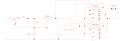
") The relays are obvs now 3PCO, so the 11-pin efforts.
The relays are obvs now 3PCO, so the 11-pin efforts.