current limiter for 12vdc 5a power supply

Thread Starter

tracecom

Joined Apr 16, 2010
3,944
I have some good 12vdc 5a regulated switching power supplies and I would like to add current limiting capability to them. Ideally, I would connect the output from an existing supply to a current limiter and then connect the load to the output from the current limiter. I would like to be able to "dial in" the current from 0a up to the maximum that the power supply will source.

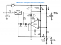
I have searched this forum and the web, but have not found a suitable circuit. The datasheet for the LM317 has a schematic for a voltage and current regulated 5a supply (on page 18,) but I lack the ability to extract the current portion.

Any help would be appreciated.
 

Attachments

Kermit2

Joined Feb 5, 2010
4,159
Look at page 18. The circuit called "1 Amp current limiter". You would put the variable resistor(use a high wattage rheostat) where the 1.2 ohm resistor is. A 10-20 Ohm rheostat would give you a wide range of current limiting.
 

Thread Starter

tracecom

Joined Apr 16, 2010
3,944
Look at page 18. The circuit called "1 Amp current limiter". You would put the variable resistor(use a high wattage rheostat) where the 1.2 ohm resistor is. A 10-20 Ohm rheostat would give you a wide range of current limiting.
K2,

Thanks. I saw that, but I don't know how to scale it up to handle 5 amps.
 

Thread Starter

tracecom

Joined Apr 16, 2010
3,944
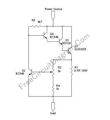
Further web searching turned up the following, but I can't really understand the description. (Maybe English wasn't the writer's native language?)

http://freecircuitdiagram.com/2008/08/27/variable-adjustable-current-limiter-circuit/

Can someone edit the description to clarify it? Does the circuit look valid? Would the positive voltage from the power supply just connect to the current limiter's input, and the ground pass through from the input to the output? Except for R1 which is 10 watts, what is the wattage of the resistors? What size heat sink is required for Q1?

I know that's a lot of questions, but I can build it if I can get the answers. So if you can help, thanks.
 

Kermit2

Joined Feb 5, 2010
4,159


Mount the power transistor on a heat sink. Use 1/4 watt resistors and a Potentiometer rated for at least 250 milliwatt and nothing should burn up. You could use a switch to change between various values of the high power resistor R1. That way you would have a wider range of current limits to work with.
 

Thread Starter

tracecom

Joined Apr 16, 2010
3,944
Mount the power transistor on a heat sink. Use 1/4 watt resistors and a Potentiometer rated for at least 250 milliwatt and nothing should burn up. You could use a switch to change between various values of the high power resistor R1. That way you would have a wider range of current limits to work with.
K2,

Would the positive voltage from the power supply just connect to the current limiter's input, and the ground pass through from the input to the output?

Thanks.
 

Kermit2

Joined Feb 5, 2010
4,159
Ground would be "Common" to both circuits.

It is not present in the circuit drawing. Consider the arrangement of transistors and resistors to be one big variable resistor with one wire on each end, and a knob to change its resistance. ;)
 
Last edited:

solis365

Joined Nov 5, 2008
21
a full featured current-limiting voltage supply would involve a current sensing circuit that switched the circuit over to a current-supply instead of voltage-supply once the current limit was hit. there IS a circuit of a very nice one online but for the life of me I can't remember the website. keep looking!
 

Kermit2

Joined Feb 5, 2010
4,159
I have some good 12vdc 5a regulated switching power supplies and I would like to add current limiting capability to them. ...


Just so you know (in case you don't) Any circuit that uses 12 volts can use those power supplies. The ONLY problem they would present you, would be the occasion where a circuit wants MORE than 5 amps of current. As long as the circuit can function with less than 5 amps of current, even if the circuit only needs 1 microamp, the 12 volt supplies you have would work for powering them.

you understand that point?
 

Thread Starter

tracecom

Joined Apr 16, 2010
3,944
Just so you know (in case you don't) Any circuit that uses 12 volts can use those power supplies. The ONLY problem they would present you, would be the occasion where a circuit wants MORE than 5 amps of current. As long as the circuit can function with less than 5 amps of current, even if the circuit only needs 1 microamp, the 12 volt supplies you have would work for powering them.

you understand that point?
Yes, but thanks anyway. I am going to use the circuit to limit the current to a PTC heating element. The element will stabilize at about 4 amps, but before it heats up, it has a brief in-rush current of about 8 amps. The 8 amps would exceed the capability of the PS which is what I am trying to avoid.

I ordered the parts today to build the circuit. In addition to the .5Ω resistor, I also ordered a .75Ω and a 1Ω. I think the .75Ω should give the range that I want: about 1 amp to 7 amps, so I can set it to limit at 5. Maybe! :)
 

bertus

Joined Apr 5, 2008
23,000
Hello,

I think you are pointing at this picture:


R3 is measuring the current in that schematic.
The current limitation is depended on the voltage accross it.
This voltage is 1.25 * ( R2 / R5 ).
At max the voltage is 1.25 * (250 / 330 ) = 0.9469 Volts.
The maximum current will be 0.9469 / 0.2 = 4.735 Ampere.

Bertus
 

Attachments

fongrang

Joined Feb 16, 2012
1
If you're thinking of exceeding 4amp or so you will need to consider whether to up the wattage of R1 or consider adding another R1 of same value in parallel.

ole git
 
Top