Current inconsistency

Thread Starter

Kris@UA

Joined Apr 29, 2017
18
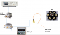
I am designing a LED transmitter(fig1). A data signal from waveform generator is sent to the amplifier and then offset by a tee-bias for providing voltage(for turn-ON) to my LED. The DC source connected to the supply/DC terminal of Tee-bias is drawing current as follows.
(1) When the RF end of tee-bias is grounded, current drawn from DC supply(as seen from PS-305D Front -panel) 1.9 V is around 0.88 A
(2) When the RF end is connected to waveform generator(signal is input to the tee-bias via amplifier) the current drawn from the source is 1.6 A for the same voltage 1.9 V
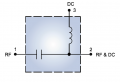
The tee-bias contains a capacitor at the input side(blocks DC current), this means only possible path for current from DC supply remains the same whether the bias input is grounded or connected to some other device. But I do not understand why there is current difference?
 

Attachments

Papabravo

Joined Feb 24, 2006
22,081
I am designing a LED transmitter(fig1). A data signal from waveform generator is sent to the amplifier and then offset by a tee-bias for providing voltage(for turn-ON) to my LED. The DC source connected to the supply/DC terminal of Tee-bias is drawing current as follows.
(1) When the RF end of tee-bias is grounded, current drawn from DC supply(as seen from PS-305D Front -panel) 1.9 V is around 0.88 A
(2) When the RF end is connected to waveform generator(signal is input to the tee-bias via amplifier) the current drawn from the source is 1.6 A for the same voltage 1.9 V
The tee-bias contains a capacitor at the input side(blocks DC current), this means only possible path for current from DC supply remains the same whether the bias input is grounded or connected to some other device. But I do not understand why there is current difference?
Is it possible that what you think is measuring a DC current is actually measuring something else?
 

Thread Starter

Kris@UA

Joined Apr 29, 2017
18
I thought of it.
My reasoning is as follows....The current coming from the DC supply directly goes to the tee-bias and the DC supply panel shows the current coming out of it and going to the tee-bias. If i am finding more current coming out of it, it means that now effective path resistance is decreased when the tee-bias input is connected with AWG/Amplifier output. which means there have to be two paths(like two parallel paths) : one to output and one back to input. But at the input side, I have measured the voltage and found it to be zero. Therefore, my reasoning is not correct.
Also, how do i check if the current whether it is actual DC current/something else?
 

Papabravo

Joined Feb 24, 2006
22,081
I thought of it.
My reasoning is as follows....The current coming from the DC supply directly goes to the tee-bias and the DC supply panel shows the current coming out of it and going to the tee-bias. If i am finding more current coming out of it, it means that now effective path resistance is decreased when the tee-bias input is connected with AWG/Amplifier output. which means there have to be two paths(like two parallel paths) : one to output and one back to input. But at the input side, I have measured the voltage and found it to be zero. Therefore, my reasoning is not correct.
Also, how do i check if the current whether it is actual DC current/something else?
Measure both AC current and DC Current. A DC measurement of an AC waveform will average the samples and produce something close to zero. The AC measurement will be unaffected by the DC current.
 
Top