Current Control using LT3092

Thread Starter

surina

Joined Nov 11, 2015
10
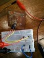
Hi all, I wanted to use LT3092 to have a current controller circuit. I want to control the current for less than 20mA. Based on the LT3092 datasheet, I already connect SET pin to 20k ohm resistor and OUT pin to 10 ohm to get Iout limited to 20mA. The IN pin is directly connected to power supply. The problem is, the circuit is not limited to 20mA. When I supply more voltage, the output current also increasing. Is there any correct way to have a current limiting circuit using LT3092?

Thank you in advance for any help.
 

crutschow

Joined Mar 14, 2008
34,280
Did you wire it per the data sheet?
Below is the LTspice simulation of your circuit with the proper connections.
As you can see the output current is constant at 20mA for any voltage above about 3.5V input as expected for an arbitrary 100 ohm load.

upload_2016-8-3_12-47-11.png
 

Attachments

Last edited:

Thread Starter

surina

Joined Nov 11, 2015
10
Post your schematic. What voltage are you applying? What is the load resistance?
I just use simple configuration just like in its datasheet. The voltage applied is from 3 up to 35V (due to limitation of my power supply). The I out seems not exceed 10mA. I tried to replace the Rout as 100ohm so the maximum current will be 2mA only. I used 1kohm as the load resistance and the current still exceeding 2mA.
 

Attachments

Alec_t

Joined Sep 17, 2013
14,280
Use the 'Upload a file' button to post a sharp close-up pic of your actual circuit. Perhaps we can spot a wiring error. If there is no error then the chip is dead/fake.
 

Thread Starter

surina

Joined Nov 11, 2015
10
Here I attach my circuit testing on breadboard attach with the LT3092. Is there any possibility the chip is dead or fake since I bought it directly from Linear Technology website?
 

Attachments

Thread Starter

surina

Joined Nov 11, 2015
10
There are some capacitors and resistors to stabilize the circuit. I am just following all the tips on the datasheet where it tells to put RC connection and bypassing capacitors together with the chip. Since the circuit does not functioning well, I cut off all the connection on the PCB and just trying to test only from the chip itself. I put jumper wire directly from the IN, OUT and SET pin and connected to the breadboard where I put Rset as 20kohm and Rout 100ohm.
 
Top