Current Bypass

Thread Starter

fady.moawad

Joined Dec 24, 2024
28
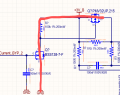
Hello all, can someone give me a hand? i was making a circuit that would act as current bypass (that flows on 1R5), basically mosfet p by closing it provides a line with lower resistance, so current flows there.

Is this gonna work well in ur opinion? the thing that makes me doubt a bit is the 100k resistor beetwen gate and source of p mos

1740404022101.png
 

crutschow

Joined Mar 14, 2008
38,503
s this gonna work well in ur opinion? the thing that makes me doubt a bit is the 100k resistor beetwen gate and source of p mos
It should work, depending on if the "Current BYP 2" signal is high enough to turn on the N-MOSFET (why do all the component designations have a (?)?)
The 100kΩ resistor is to provide a zero Vgs bias to the P-MOSFET when the MOSFETs are off, which should be fine.
 

Thread Starter

fady.moawad

Joined Dec 24, 2024
28
It should work, depending on if the "Current BYP 2" signal is high enough to turn on the N-MOSFET (why do all the component designations have a (?)?)
The 100kΩ resistor is to provide a zero Vgs bias to the P-MOSFET when the MOSFETs are off, which should be fine.
yes i did this also to limit the current, which in this application i dont really need. ye for that no worries im using an esp32 so gpio are at 3.3V
 

Thread Starter

fady.moawad

Joined Dec 24, 2024
28
It should work, depending on if the "Current BYP 2" signal is high enough to turn on the N-MOSFET (why do all the component designations have a (?)?)
The 100kΩ resistor is to provide a zero Vgs bias to the P-MOSFET when the MOSFETs are off, which should be fine.
but the 100k resistor doesnt make my current path having another impedance?, like when n mosfet is closed and p mosfet also. from drain to source the circuit is closed ( for both mosfet). So basically there is mos n GND-drain-100k resistor-drain ( so this path sees the 100k resistor or am i wrong?
 

Thread Starter

fady.moawad

Joined Dec 24, 2024
28
The 100k resistor biases the Vgs of the P-MOSFET to 0V so it turns off, when the N-MOSFET is off.
No need for a resistor from source to drain.
no wait u didnt get what i meant, when the mosfet N is on ( so the circuit beetwen drain and source is closed of the n mos) the gate of p is pulled to 0V at this point the mosfet p is in conduction mode too, cus vgate is at 0v, at this point what we can see is a path from drain to source of p mos - resistor - drain source of n mos, no? it works like this right? and my question was, if it works this way we wouldnt have this path created by the 2 mosfet that got a resistor of 100k beetwen?
 
Sorry, I don't really understand your question.
And please use English words, not text-speak.
This was work account, btw what i meant is basically this u can see in the image. the mosfet n conducts and pulls gate to gnd so p starts conducting too from drain to source, so current sees that "red" current path to 0 gnd, but by seeing that path the current doesnt also see the 100k resistor?
 

Attachments

Of course.
But why are you concerned about that?
The small current comes from the +3V supply and has no effect on the output circuit.
Im concerned because like that the current gonna see a high resistor path no? second path would be the 1.5Ohm resistor. so 100k is much higher than that, or i misunderstood something?
 

crutschow

Joined Mar 14, 2008
38,503
like that the current gonna see a high resistor path no? second path would be the 1.5Ohm resistor. so 100k is much higher than that, or i misunderstood something?
You appear to be misunderstanding.
There are two separate current paths from the voltage source, which typically has negligible resistance.
The currents are not in series but in parallel.
So the current through the load is unaffected by, and unrelated to, the current through the 100k resistor.
Both currents flow in parallel from the supply to ground through the resistor and the load.
can u show me how current flows in that case? in case mosfet n closes?
 
You appear to be misunderstanding.
There are two separate current paths from the voltage source, which typically has negligible resistance.
The currents are not in series but in parallel.
So the current through the load is unaffected by, and unrelated to, the current through the 100k resistor.
Both currents flow in parallel from the supply to ground through the resistor and the load.
I didnt get it tbh.. so current doesnt flow from drain of mosfet p to gnd of mosfet N?
 

crutschow

Joined Mar 14, 2008
38,503
so we dont use the path made by mosfet n and p to connect to gnd?
Of course we do.
You just seem to have the current direction for one of them wrong.
The current flows from the 3.3V through the 100k resistor and N-MOSFET (drain-to-source) to ground, and also from the 3.3V through the P-MOSFET (source-to-drain) and the 1.5Ω load to ground.
Don't see why that's hard to understand. :confused:
I had a misunderstanding, but now i understood, thanks.
 
Top