CRT safety concerns for my custom CRT tube case

Thread Starter

Domarius

Joined Sep 1, 2013
46
I would greatly appreciate any opinions on my design, particularly in regards to electrical safety with CRT tubes.

The TV is too wide to fit inside my custom arcade cabinet due to the built in speakers on the side. So I designed this custom case so that it could sit inside my arcade cabinet without the extra width from the built in speakers, and still be electrically safe and keep the motherboard etc. protected from bugs and dust.

Here's a video showing the situation, it's 5 minutes long;

For those who don't have time for the video, here are some screenshots (but the video does provide more info).

Exterior of the cabinet (these are not its actual colours)
1634266426212.png

Side view of my monitor case sitting inside the cabinet, with the cabinet walls hidden
1634266583322.png

Exterior view of my custom CRT case, the actual object in question
1634266603239.png

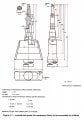
The front bezel hidden, revealing the air gap I left around the high voltage area of the CRT, which I'm respecting from the original case design. I've highlighted some objects:
  • The lighter coloured horizontal blocks of wood are structural pine. The rest of the case is made with 16mm MDF.
  • The original mounts on the tube itself are being bolted into some corner braces that I found at Bunnings.
  • At the bottom are 2 MDF blocks that the tube is sitting on, which was also in the original case, but they were made of sturdy plastic
  • On the left and right sides, I highlighted the screws that hold on the front bezel (hidden) these are edge drilled in and I hope, are sufficiently hidden away from the voltage around the front of the tube, since these screws directly lead out to the front, exposed.

1634266653541.png

These holes drilled in for ventilation are only on the sides and bottom, and covered internally with a metal mesh. The bottom floor is elevated by 5mm leaving a gap underneath at the back. The walls and front are the only points contacting the ground directly.
1634266675722.png

Just a side view with the walls removed, the motherboard (grey stuff below) is mounted on the floor of the case in roughly the original position it had inside the original case.
1634266694873.png

For lifting, these gaps in the side near the front are hand holds, and they will be covered when in use, to keep the bugs out. I hope they are far enough from the front to reasonably avoid electrocution from the high voltage area during a normal lifting movement. When lifting, the combination of the mounts and brackets (as shown previously) mounted on the pine planks, screwed into the MDF walls as shown below, is what will be bearing all the weight.
1634266713347.png
 

Attachments

metermannd

Joined Oct 25, 2020
343
I was an arcade tech for a few months many moons ago, and if memory serves me correctly, the CRT assembly was typically mounted "bare" with a bracket to support the main board, and a cable running to the arcade board (usually bolted to standoffs on the wall), and the power supply usually was on the 'floor' of the cabinet.

If there won't be any hands poking into the cabinet while in use, I think you might be able to get away with an "open box" that allows the components to be properly supported and for the monitor assembly to be handled as an unit.
 

DickCappels

Joined Aug 21, 2008
10,171
The fiberboard should not be able to sustain a flame if you take a flame to it. If it can sustain a flame for more than a few seconds after the flame has been removed, find some material that won't.

All of the metal bits around the front of the tube should be wired together and connected to the ground strap on the Aquadag coating on the back of the CRT -this is so that they don't charge up to the anode voltage and possibly arc to other places and maybe start a fire.

Make sure there is plenty of ventilation -those tubes dissipate significant power, and the electronic components should be checked as well for temperature rise above room temperature.

There should already be a tension band (a metal strap) around the circumference of the bell over the faceplate. If not, get a different tube. The band is there so that in case the faceplate cracks the glass won't go flying all over the room, possibly injuring somebody.

The Aquadag coating on the CRT should we connected, preferably with an 8mm briad or wider (for low impedance), to the CRT socket board upon which the spark gaps protecting the circuitry should be located. The, after the CRT socket board, it should go to the proper ground near the flyback transformer.

Color or monochrome? If color it is a good idea to start with the degaussing coil that was originally used with the CRT. Try to duplicate any magnetic material associated with the degaussing coil(s) if there is any. You may need to tweek the magnetic design of the degaussing flux path -you will know when you turn on the TV.

Check the AC leakage from chassis ground to earth by measuring the AC voltage drop across a 1k resistor. If it is more than 15 milliamps, it would be a good idea and find out why then correct the situation.
 

Hymie

Joined Mar 30, 2018
1,284
The product safety standard IEC 62368-1 requires that the product fire enclosure is made of minimum V-1 flame rated material (on the proviso that there are no arcing potential ignition sources within 13mm of the enclosure). Based on your drawings, it would appear that there are no electrical components within this distance of the enclosure. The good news is that wood and wood-based material with a thickness of at least 6mm is considered to meet this requirement (V-1 rating).

For the purposes of the fire enclosure ventilation, holes within the enclosure top should be a maximum of 5mm in diameter, holes in the base should be a maximum of 3mm in diameter, or may be a maximum of 6mm if under internal material with the minimum flame rating of V-1. Side apertures are only limited by not allowing access to hazardous parts within the product.
 

Hymie

Joined Mar 30, 2018
1,284
Prior to committing to the enclosure design, I’d recommend that you determine the total power dissipation within the cabinet (for the purposes of test this can be considered as the power draw). Then conduct a test dissipating this power level with the vents you propose.

If the internal enclosure temperature rise is much above 50K, then the life of the CRT is likely to be compromised. You may need to add additional holes within the enclosure, or even add a fan providing forced ventilation/cooling.
 

DickCappels

Joined Aug 21, 2008
10,171
(some text removed for clarity)
If the internal enclosure temperature rise is much above 50K, then the life of the CRT is likely to be compromised. You may need to add additional holes within the enclosure, or even add a fan providing forced ventilation/cooling.
Do you mean °C? 50K is really, really cold! :)
 

MrSalts

Joined Apr 2, 2020
2,767
Do you mean °C? 50K is really, really cold! :)
No, typically 50K temp rise. Units are the same as 50 °C but the standard has been changed in the 1990s to describe temp rise as K because, by convention, K does not use the ° symbol which was not easily accessible on windows/DOS computers.
A similar convention is used for heat conduction by using the unit W/(m*K)
 

Thread Starter

Domarius

Joined Sep 1, 2013
46
Thanks everyone, sorry for the late reply. I have been looking at this thread, and thinking deeply about the project, when I have the opportunity around my shift work and some other stuff. Because of the whole deadly 25k voltage thing, I'm trying to take a measure 100 times, cut once approach XD

If there won't be any hands poking into the cabinet while in use, I think you might be able to get away with an "open box" that allows the components to be properly supported and for the monitor assembly to be handled as an unit.
Prior to committing to the enclosure design, I’d recommend that you determine the total power dissipation within the cabinet (for the purposes of test this can be considered as the power draw). Then conduct a test dissipating this power level with the vents you propose.
I designed the cabinet to be "TV tube agnostic", the idea is; over the life of the cabinet, I'll have to replace TVs, since they might die one day, as they'll always be old and 2nd hand as no one is making CRT TVs anymore. Finally when the last CRT is long gone, there will hopefully be some kinda OLED TV solution (being the only technology that can achieve the contrast ratio of a good CRT) when they're less cost prohibitive, and something that'll fit vertically to maintain the 4:3 aspect ratio. That's the plan anyway.

So I've kinda ended up in this situation where the TV was too wide to be included case and all, so the only reason I'm making a new case is so I can have the speakers removed so it'll fit.

There should already be a tension band (a metal strap) around the circumference of the bell over the faceplate. If not, get a different tube. The band is there so that in case the faceplate cracks the glass won't go flying all over the room, possibly injuring somebody.

The Aquadag coating on the CRT should we connected, preferably with an 8mm briad or wider (for low impedance), to the CRT socket board upon which the spark gaps protecting the circuitry should be located. The, after the CRT socket board, it should go to the proper ground near the flyback transformer.

Color or monochrome? If color it is a good idea to start with the degaussing coil that was originally used with the CRT. Try to duplicate any magnetic material associated with the degaussing coil(s) if there is any. You may need to tweek the magnetic design of the degaussing flux path -you will know when you turn on the TV.
@DickCappels I'm glad someone with so much knowledge of CRTs has replied. This tube is a complete TV currently still in its case, awaiting the transplanting proceedure into my custom case (so it'll fit in the cabinet), and the only thing I'm removing apart from the plastic case itself, is the built in speakers. Everything else is staying with it, and I have visually confirmed it comes with the things that match your description;
  • that metal strap "tension band" around the front
  • the 8mm braided wire running from several points connected around the tube, to the circuit board (which I assume then goes to ground)
  • It's colour, but as I'm only removing the case, and the built in speakers, and taking everything else with it, I assume all this magnetic material is included somewhere.

Here's a pic of it with the back off. It's a Panasonic TX-029FJ50A
20200804_072014.jpg

On that note, I'm unsure about the procedure for lifting this extremely heavy yet extremely fragile glass tube, so I've come up with a way involving two people and some wide packing straps or a large blanket, having the new case already mostly made, and with both the old case and new case face down next to each other, lifting the tube straight from its old case into the new case. Any tips on managing this would be appreciated.

Check the AC leakage from chassis ground to earth by measuring the AC voltage drop across a 1k resistor. If it is more than 15 milliamps, it would be a good idea and find out why then correct the situation.
Hopefully it's fine - actually that's one of the problems with the previous CRT TV I had in the cabinet that I hopefully have seen the last of; handling any of the AV cables out the back would give you an unpleasant zap if you touched any of the metal part of the plug. It made me wonder what long term damage that would be doing to the PC I had it plugged into (for S-Video out) so I'm very glad that TV is gone. I haven't noticed any such problem with the new TV, it's quite a new model, at the end of the production of CRTs, it's a flat screen.
The fiberboard should not be able to sustain a flame if you take a flame to it. If it can sustain a flame for more than a few seconds after the flame has been removed, find some material that won't.
For the purposes of the fire enclosure ventilation, holes within the enclosure top should be a maximum of 5mm in diameter, holes in the base should be a maximum of 3mm in diameter, or may be a maximum of 6mm if under internal material with the minimum flame rating of V-1. Side apertures are only limited by not allowing access to hazardous parts within the product.
Thanks guys. I will try the flame test on some of the off-cuts I already have laying around. The front panel is 6mm MDF, and it's flush up against the front of the flat screen tube, hopefully this is OK??

And the hole sizes, is this about not having them too big to hopefully starve any internal flame? So this is a balancing act between ventilation and fire safety? The vents on the original plastic case are tiny little slits all around the sides and base, each about 3x10mm, across a large surface area of about 20x20cm on the sides, similar situation on the back and underneath. I was going to roughly replicate that, but I was going to use my larger 6mm drill bit, but after your advice, I could use the 3mm drill bit underneath and the 5mm drill bit on the sides and back, how does that sound? The exception for 6mm if under internal material with the V-1 flame rating, could be the situation underneath the motherboard, I assume the motherboard PCB must have this flame rating?

The product safety standard IEC 62368-1 requires that the product fire enclosure is made of minimum V-1 flame rated material (on the proviso that there are no arcing potential ignition sources within 13mm of the enclosure). Based on your drawings, it would appear that there are no electrical components within this distance of the enclosure. The good news is that wood and wood-based material with a thickness of at least 6mm is considered to meet this requirement (V-1 rating).
Yes I believe this is the case... the mounts are mounted to the metal corner brackets you can see in my design, which themselves are screwed directly into the 16mm MDF and 35mm structural pine. The metal screws holding the 6mm MDF front are embedded into the edge of the 16mm MDF so aren't exposed to the inside, so this should be ok. There is an air gap around the "tension band" around the front, as shown in the design, but as mentioned, the 6mm MDF is hard up against the front of the tube (mimicking the design of the plastic case). Hopefully this is OK? Here's a close up of this situation with the side removed. The screws are visible still - those inward pointing ones will be embedded in the wall.
1634708595713.png

If the internal enclosure temperature rise is much above 50K, then the life of the CRT is likely to be compromised. You may need to add additional holes within the enclosure, or even add a fan providing forced ventilation/cooling.
I'm going to pay attention to the heat coming out of the holes during usage, I'm willing to complete the design and then see if the amount of heat coming out is noticeably different to my hand during use than in its original case (which was pretty much no heat at all) and re-do the walls and base if needed. Definitely willing to consider installing a fan, just have to be sure that having it syphon off the incoming voltage doesn't affect the operation of the TV in any way... I haven't done that before so am open to looking into how to do this safely if need be.
 

MrChips

Joined Oct 2, 2009
30,806
Little critters are known to enjoy warm places to inhabit and raise a family. Make sure that there is no single hole larger than 4mm.

I have seen a mouse build a nest using toilet paper in an IBM PC right on top of the math coprocessor, the warmest component on the PCB.
(A true story of a PC that grew its own mouse.)
 

Thread Starter

Domarius

Joined Sep 1, 2013
46
Little critters are known to enjoy warm places to inhabit and raise a family. Make sure that there is no single hole larger than 4mm.

I have seen a mouse build a nest using toilet paper in an IBM PC right on top of the math coprocessor, the warmest component on the PCB.
(A true story of a PC that grew its own mouse.)
Heheh thanks man. Yeah the holes are going to be covered from the inside with mesh.

I've had my experience with geckoes leaving urine streaks on the inside of the protective acrylic screen and droppings on the inside of the cabinet, at the last place I was renting, which was particularly bad for that. Not sure I want to put a back on the cabinet yet but definitely ensuring my custom TV enclosure is secure from intruders.
 

Thread Starter

Domarius

Joined Sep 1, 2013
46
All of the metal bits around the front of the tube should be wired together and connected to the ground strap on the Aquadag coating on the back of the CRT -this is so that they don't charge up to the anode voltage and possibly arc to other places and maybe start a fire.
Uh oh, I think what you're referring to is exactly what I've ended up with; I found a grommet that fits the mount hole exactly, it buffers both sides of the mount the way I wanted it to (because it will be leaning back slightly in the cabinet, but also will be face down momentarily for maintenance), but it also electrically separates the bolt and bracket from the front of the tube. See attached photo.

(Please note, the order of the bracket and washer is not final, I just put it together to test the thickness it would all take up, but in doing so I recognised this connectivity issue you outlined.)

No contact.png

So to address this issue, I must securely fix some wire from the mount to the bolt somehow. Or from the bolt to the ground strap.
 

DickCappels

Joined Aug 21, 2008
10,171
That would be my approach, but you could also measure the voltage from bracket to ground after running the monitor for a few minutes. It might be that the bracket "sees" the Aquadag coating rather than something connected to the anode.
 

djsfantasi

Joined Apr 11, 2010
9,163
As far as fireproofing, no one has mentioned fire resistant paint? Is that use not acceptable in electronics?

In a theatrical paint shop, we maintain a supply of NFPA rated fire resistant black paint. All sets have a coat of this paint before scenic painting is applied (and the scenic paint has a fire resistant additive).

Couldn’t this be used on the case?
 

BobaMosfet

Joined Jul 1, 2009
2,113
You'll know if you break the tube in handling it- you'll hear a tinkle/pop sound, and then it'll implode. CRT is a cathode ray gun- shooting rays directly at you, hitting phosphor coating on inside of tube. Powerful magnets around the neck of the tube are what is used to control where the ray points it's beam on the screen. As such, other than electrical safety and fire concerns, you want to maintain EMF shielding around it if you defeated any that existed.
 

DickCappels

Joined Aug 21, 2008
10,171
You'll know if you break the tube in handling it- you'll hear a tinkle/pop sound, and then it'll implode. CRT is a cathode ray gun- shooting rays directly at you, hitting phosphor coating on inside of tube. Powerful magnets around the neck of the tube are what is used to control where the ray points it's beam on the screen. As such, other than electrical safety and fire concerns, you want to maintain EMF shielding around it if you defeated any that existed.
The reason that CRTs are highly evacuated is because "loose" electrons don't travel very far in air as well as other reasons. It is always a good idea to keep things near a high voltage source that are not supposed to be at a high voltage grounded, but getting drilled by an electron beam has never been a worry and that's after 25 years designing and working with CRTs.

@Domarius I could not tell from the image if your post #11 whether those bolts are connected to any large pieces of metal. The smaller the are the less you should worry about them. If they connect to the tension band around the front of the tube and if the tension band is not in contact with the black Aquadag outer coating, then you should add a ground connection. If it is little more than a bolt, washer and a bit of mounting ear then there is little or no point in grounding them.
 

Thread Starter

Domarius

Joined Sep 1, 2013
46
If they connect to the tension band around the front of the tube and if the tension band is not in contact with the black Aquadag outer coating, then you should add a ground connection. If it is little more than a bolt, washer and a bit of mounting ear then there is little or no point in grounding them.
Hmm ok - I think actually I mis-read this statement below to be refering to metal bits that I might add. For clarification, in the quote below;
All of the metal bits around the front of the tube should be wired together and connected to the ground strap on the Aquadag coating on the back of the CRT -this is so that they don't charge up to the anode voltage and possibly arc to other places and maybe start a fire.
... are you referring to the construction of the tube itself? It is a perfectly working (new-ish) TV, so if by "metal bits" you're referring to the tension band etc. that the tube is supposed to come with, then yes I can confirm everything is wired together correctly.
So if my "metal bits" that I added just to mount the tube to the frame are of no concern, then I won't bother grounding them.
As far as fireproofing, no one has mentioned fire resistant paint? Is that use not acceptable in electronics?
I'm open to doing this, but older TVs were made of wood, did they do this?
 

DickCappels

Joined Aug 21, 2008
10,171
I'm open to doing this, but older TVs were made of wood, did they do this?
I don't know whether this was done but it is a very good bet that the cabinets had to pass an Underwriter's Laboratories flammability test before being released for manufacturing.

If your bits of metal are small, then I agree -skip the grounding if you don't mind a little zing if accidentally touching the floating parts while working on the display.
 

Thread Starter

Domarius

Joined Sep 1, 2013
46
The product safety standard IEC 62368-1 requires that the product fire enclosure is made of minimum V-1 flame rated material (on the proviso that there are no arcing potential ignition sources within 13mm of the enclosure). Based on your drawings, it would appear that there are no electrical components within this distance of the enclosure. The good news is that wood and wood-based material with a thickness of at least 6mm is considered to meet this requirement (V-1 rating).

For the purposes of the fire enclosure ventilation, holes within the enclosure top should be a maximum of 5mm in diameter, holes in the base should be a maximum of 3mm in diameter, or may be a maximum of 6mm if under internal material with the minimum flame rating of V-1. Side apertures are only limited by not allowing access to hazardous parts within the product.
Just wanted to thank you specifically for this fire safety recommendation, it gave me piece of mind when recently re-designing the ventilation (right before I go to jigsaw everything XD).

I'm willing to go the extra effort and make sure all these little holes in the base are 3mm, keeping them this small serves the dual purpose of adhering to the standards you mentioned, but also means I'll skip nailing down a metal fly-screen type mesh behind it, removing any shorting risk underneath the motherboard that will be mounted to the base.
1637804918267.png

But since you mentioned side vents don't have any size requirement, I'll open them up to 1cm tall and make them long slits that I can more easily jigsaw, and nail some mesh behind them. Providing lots of ventilation and saving me a tonne of time.
1637805107987.png

The layout of the vent holes roughly match the ventilation layout of the original case - they are all along the base, and back wall, but only on the back half of the side walls (I assume so the tube itself is less exposed?) and there are none on the top of the case at all, I assume to prevent dust gathering up on the components. (Which seems to work; there was practically no dust inside when I first opened it.)
 

Hymie

Joined Mar 30, 2018
1,284
Attached is the drawing for the test probe V.1 from IEC 62368-1, which represents a child’s finger.

The probe is applied to the enclosure (and openings therein) with a force of 30N and must not access hazardous parts.
Without having a physical probe it is difficult to determine compliance for a given constructional opening. But with careful examination of the probe dimensions, you should be able to calculate the probe penetration distances (given the size of the enclosure openings) – and whether any hazardous internal parts would be accessible to the probe.
 

Attachments

Hymie

Joined Mar 30, 2018
1,284
Further to my post above, the enclosure is required to withstand a force of 250N applied via a disc 30mm in diameter for 5 seconds and an impact from a 500g steel ball* falling through 1.3m (applied to the top and sides of the enclosure).

After the above tests, the enclosure is required to continue to provide protection against access to hazardous parts – so besides meeting the accessibility requirements (applying the test probe V.1) it must be sufficiently robust to withstand the above mechanical force/impact tests.

* the steel ball is approximately 50mm in diameter – the resultant impact energy being around 6.5J.
 
Top