Creating an LED flickering candle light board

Thread Starter

Jason-9000

Joined Apr 18, 2024
4
Howdy all and thanks for the help in advance.

I thought I’d approach this topic from a reverse engineering angle! I’m trying to figure out how this tiny board that drives 3 discrete small flickering LEDs works.
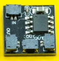
Screenshot 2024-04-12 102320.png

I know you can buy small lights with flicker built in but I want to understand what’s under the hood so I can create small boards to hide in dioramas, etc. Thoughts / questions:

- Main controller chip? Research points me to Attiny chips but I’ve also come across a few other options. What are we seeing here, I wonder.

- Variation in the flicker? This depends on the code as well as the outputs on the chip, correct? This example has 3 outputs. I’m not a programmer but I can do simple sketches on the Arduino and I'm also open to other simple options.

I’ve done some low-level THT soldering on small boards with tiny lights (0402, 0603, 0805) and appropriate resistors for 5V, small connectors (JST ZH), etc. I’ve also created a simple power hub board in KiCad so I have an idea of the basics but I’m still a beginner.

Essentially, I’m eager to figure out something tiny, cheap, and not too crazy! Any ideas where to start?
 

KeithWalker

Joined Jul 10, 2017
3,196
An ATTINY85 would do the job running on 5V (USB?). The eight pin DIP can drive up to 5 individual outputs. It is available as surface mount and through-hole versions. There are a number of posts on-line that explain how to program it, using an Arduino Uno. The basic simple test program is called "Blink". It flashes a LED on and off at 1 second intervals. That would be a very simple introduction for you and could be modified to experiment with a flicker effect.
 

dl324

Joined Mar 30, 2015
17,222
Welcome to AAC!
Essentially, I’m eager to figure out something tiny, cheap, and not too crazy! Any ideas where to start?
The IC is likely a microcontroller. There may be some software you can use to dump the code, but it'd probably be less bother to start from scratch. And you'd avoid any potential issues with stealing proprietary information.
 

Sensacell

Joined Jun 19, 2012
3,509
Step 1- define exactly what the goal is.

Analyze how the existing products function, what the current waveform looks like through the LEDs.
Then you can design an algorithm that can reproduce the behavior.
 

Thread Starter

Jason-9000

Joined Apr 18, 2024
4
Thank you so much for the replies, I appreciate it!

@dl324 I'm curious, what do you think that microcontroller might be? Should I just get myself an Attiny and dive in on a breadboard and see what happens - learning more Arduino code (I've already learned the blink code and some other intro programming) and going from there? Most of this is just me trying to sleuth things out and play and eventually see what small PCB I can create.

Thanks!
 

Ya’akov

Joined Jan 27, 2019
9,277
Thank you so much for the replies, I appreciate it!

@dl324 I'm curious, what do you think that microcontroller might be? Should I just get myself an Attiny and dive in on a breadboard and see what happens - learning more Arduino code (I've already learned the blink code and some other intro programming) and going from there? Most of this is just me trying to sleuth things out and play and eventually see what small PCB I can create.

Thanks!
Welcome to AAC.

The MCU seems to be marked but it is illegible. Are there really markings on it? If you also have trouble reading it, you can use something like White Out correction fluid, or a brightly colored paint marker to make it visible—just a tiny drop, then press and wipe it off. Even without the enhancment it might be readable from some particular angle.

That said, even if you identify the chip, it is unlikely to do you any good as the firmware will almost certainly not be accessible. The one chance of gaining from it is if it happens to be an MCU you can re-flash with your own code—that would simplify construction since they’d have done it for you. Or if by some miracle the pinout is compatible with something you can use for yourself.

As far as using the ATTinyXX—I’d say it would be an excellent choice. Cheap, capable, needs almost no external parts—and it is compatible with the Arduino ecosystem through well maintained cores. It’s certainly not the only choice, but I wouldn’t hesitate to recommend it. I have used an ATTtiny85 to control several WS8212 type RGB LEDs with excellent results, and the Arduino FastLED library worked perfectly.

One more thing: could you describe what your goal is? That is, what problem will this be a solution to? We are helping in the dark (so to speak) at this point.
 
I remember reading about fifteen years ago someone hooked a loudspeaker to a flickering LED mock tealight and it played a tune! If you look at greetings card tune chips (usually three pin items running off low voltages) they produce what appears to be random voltages that could be hooked to an LED. Small space taken up, low tech solution. UM66, M66, those kinds of chips.
 

BobTPH

Joined Jun 5, 2013
9,339
As @Ya’akov said, identifying the microcontroller will not gain you anything. Any microcontroller can perform this function, assuming you can program it to do so.

When I was first learning microcontrollers, I set out to match the look a the cheap flickering LED candles.

My first attempt, from which I did not expect much, was as follows:

Use a random an 8 bit random number generator to come up with a duty cycle for a PWM output and output the PWM to a port pin with an LED + resistor connected.

Repeat every 100ms. with a new duty cycle.

Much to my surprise, it worked perfectly.
 

Thread Starter

Jason-9000

Joined Apr 18, 2024
4
Thanks for the responses!

@Ya'akov thanks for the details. Here's a little more about what I hope to do:

- Create as small a board as possible running on 5V to hide in small dioramas for fireplaces, candles, etc. The more outputs the better but I was thinking 3 - 5 would be fine and I can also chain a few PCBs as needed.

- Avoid overkill. I've been trying to avoid running things off of the Arduino directly to try and simplify and keep as discretely electronic elements as possible.

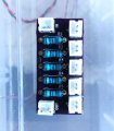
- Practice, practice, practice! I recently made a small PCB template in KiCad and ordered a few boards - about 3/4 in by 1.5 in - to make some simple 5V power hub of 4 connections with resistors and JST ZH connectors and it was a fun challenge.

J_PCB_SM.jpg


I've also played around with 555s and transistors to get a slow smooth fade in and out blinking light.

Secondary thoughts - try my hand at SMD instead of THT

Hope that helps give you some guidance on my goals.
 
Top