Creating 500mv power supply from battery

Thread Starter

Gsalet

Joined Aug 8, 2017
21
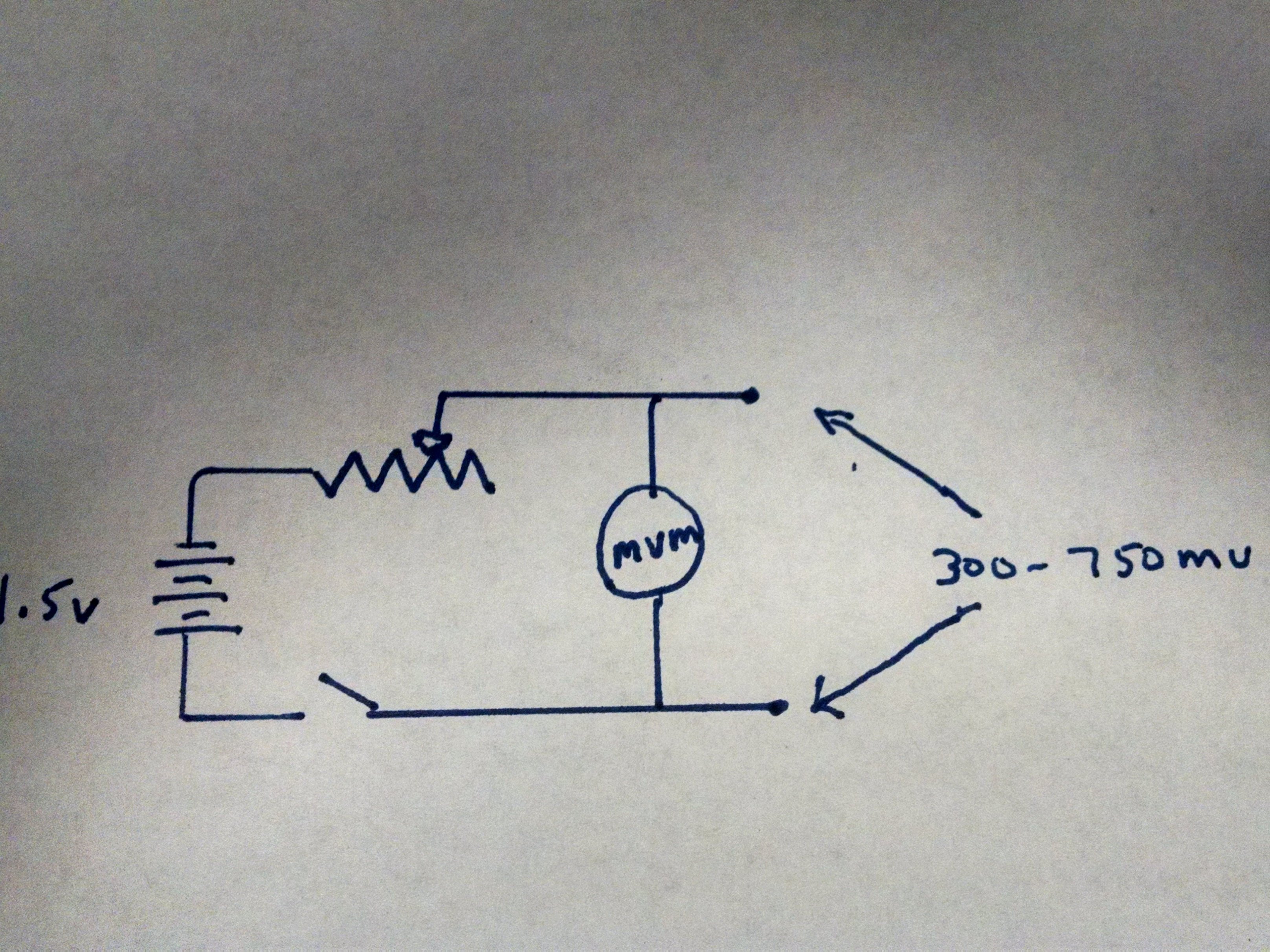
I am trying to make a power supply for testing gas valves that use thermopile for energy. My concept was to use a 1.5v battery and reduce the voltage to approximately 500mv using a resistor. I think my problem is the amount of current being required by the gas valve coil.
Here is what i know : voltage = 500mv resistance for gas valve coil 1.5 - 3.5 ohms
I come up with 0.125 amps?? .5v x 2.5 ohms = .125 I know that is not right <GRIN> where did I go wrong??

Thanks
George
 

ebeowulf17

Joined Aug 12, 2014
3,307
Regarding your calculations:
IMG_4040.JPG
Since you want to know amps, and you've got voltage and resistance:
I = V / R
I = 0.5 / 2.5
I = 0.2A (or 200mA)

As for testing things with a battery and a resistor, that's generally the worst way to deliver a desired voltage to a load. Not only does it waste lots (2/3 in this case) of the total energy as heat dissipated by the resistor, but the voltage varies depending on the resistance of the load. Solenoids aren't linear loads, so if you do like you've described, you'll end up providing variable voltages to the valve, not the 500mV you want.

Better solutions would be a buck converter (more efficient) or a linear regulator (simpler and probably cheaper.) You might also be able to get reasonable results simply using diodes to drop the excess voltage, maybe one standard and one or two Schottky diodes?
 

ebeowulf17

Joined Aug 12, 2014
3,307
Hmmm, on second thought, I think most of the odd, non linear solenoid behavior I was thinking of is specific to AC solenoids. It may be simpler and more predictable with DC solenoids. Not sure, sorry.

We'll have to see what some of the more experienced folks here recommend!
 

be80be

Joined Jul 5, 2008
2,073
Why not test them like its done with a ohm meter. Just asking i look them up some are 3.1 to 3.6 some a little lower you look it up and find it
SIT 820 ‐1.75 to 2.75 R
Honeywell VS8420 ‐3.1 to 3.6 R
Robert Shaw/Dexen – 1.5 to 1.7 R
Read the voltage of the thermocouple itself
If its good 500 to 750 most are when gas valve is off.
drop to about half when valve is on.

Not careful there easy messed up and if you really feel like testing at 500mV use a torch and new good thermocouple. Be a lot easier then messing up a valve.
 

Thread Starter

Gsalet

Joined Aug 8, 2017
21
We repair gas fireplaces our problem is that most of our parts are special order, when we roll on a job we check the thermocouple , the thermopile and measure the resistance on the gas valve. we have had experience were the coil is good but the valve will not operate, which then requires a second trip and a upset customer. My idea is to have a power source so we can check the valve before any work other than diagnostic is performed. Open to all ideas (using a torch is a little risky in a living room but a good idea)
 

dl324

Joined Mar 30, 2015
17,200
My concept was to use a 1.5v battery and reduce the voltage to approximately 500mv using a resistor. I think my problem is the amount of current being required by the gas valve coil.
Here is what i know : voltage = 500mv resistance for gas valve coil 1.5 - 3.5 ohms
Using a resistor to drop battery voltage is a poor idea because it depends on battery voltage.

Post a schematic of what your proposed tester circuit would look like. And what your go no-go criteria are.
using a torch is a little risky in a living room but a good idea
What's risky about it? You'd have to do something stupid for it to be dangerous.
 
Last edited:

Thread Starter

Gsalet

Joined Aug 8, 2017
21
This drawing is my original concept

Notice the pot and millivolt meter in my circuit to adjust for battery deviations
My goal is that the final product would have two power outputs 18mv and 350-750mv, the gas valves we are testing use both at the same time.
I am not adverse to using another circuit that would provide a reliable output

What's risky about it? You'd have to do something stupid for it to be dangerous.
It is not about being dangerous, customers won't let Techs in their homes because they smell cigarettes, Imagine firing up a torch to heat some thermocouples, Besides a piece of test equipment is much more impressive <GRIN>

Thanks for all the help and suggestions
 

dl324

Joined Mar 30, 2015
17,200
My goal is that the final product would have two power outputs 18mv and 350-750mv, the gas valves we are testing use both at the same time.
The problem with your idea is that if you set the voltage with no load, the voltage will drop as soon as you put a load on it.

You said that the resistance of of the coil could be as low as 1.5 ohms. That would draw 1/3A. Power dissipation figures for pots are for the entire resistance. When used as a rheostat, you can easily burn out the pot.

At first you mentioned 500mV, now you're giving two voltages and one of them is a range. What voltages do you want and how much current do you need from each voltage?
 

WBahn

Joined Mar 31, 2012
30,331
How about a circuit that ramped the voltage up while you monitored it with a meter and then you could note where the valve tripped, if it did? You could also monitor the current if you wanted to.
 

Thread Starter

Gsalet

Joined Aug 8, 2017
21
I am trying to duplicate a PG9 Thermopile which when factory fresh produce 750MV as they age they deteriorate, I have not been able to find the current they produce. That is why I shared the lower number of 500mv and the resistance of the coil that is operated by the voltage produced by the thermopile.
Attached is the spec sheet for the thermopile to be mimicked part no Q313

The problem with your idea is that if you set the voltage with no load, the voltage will drop as soon as you put a load on it.
That is correct Just like a thermopile does

Thanks for the help
 

Attachments

Base your design off the LM10 and the LT1010. The LM10 has a 200 mV reference and the LT1010 is good for 150 mA.
You could use a 5V USB supply if <100 mA or say a 12 V wall wart. If you want you can make it adjustable from say 400 to 750 mV

With a little more work, you could add a DPM (digital panel meter).
 

Reloadron

Joined Jan 15, 2015
7,580
Here is what i know : voltage = 500mv resistance for gas valve coil 1.5 - 3.5 ohms
Maybe there is a better way to look at or do this. The thermopile is just a pile of thermocouples in a sense. The idea being a thermopile delivers a higher voltage and more current than a thermocouple. It needs to since the coils in gas solenoids are pretty low resistance. So looking back to the beginning and a few common numbers we have coil resistances of for example 1.5 to 3.5 Ohms and a average thermopile can output 500 to 750 mV give or take. Ebeowulf used ohms law and got about 200 mA. We have .5 Volt / 2.5 Ohms = 0.2 Amp.

Making a thermocouple simulator or from old days a milli-volt pot is not difficult where the problem comes in is the required current which rules out most TC simulators. I wonder what would happen if rather than apply a voltage to the coil we apply a current and just measure the subsequent voltage drop increasing current till the solenoid valve clicks. A very simple constant current source could be made using a common op-amp and a single transistor like a 2N2222 which for short periods of time could likely handle 0.5 Amp (500 mA). The circuit would be a voltage controlled current source. Voltage control off a potentiometer.

What I am unsure about is how well this approach would work? There are companies like Calex who sell turn key solutions programmable current sources but a simple operational amplifier single transistor current source could likely be put together for about ten bucks. Does anyone see this as a viable solution?

Ron
 

WBahn

Joined Mar 31, 2012
30,331
Another potentially viable programmable current source only needs a couple transistors, and a few resistors, and a pot. A simple current mirror should work fine provided suitable ballast resistors are used.
 

ebeowulf17

Joined Aug 12, 2014
3,307
Ebeowulf used ohms law and got about 200 mA. We have .5 Volt / 2.5 Ohms = 0.2 Amp.
I did calculate that, but as I've read more of the discussion, I've begun to doubt the relevance of that calculation.

I hadn't considered how imperfect of a voltage source the thermopile is. Based on @be80be's comment, it sounds like the actual loaded voltage is half of the open loop voltage, meaning the target current for testing is presumably half as well.

I guess I don't know how critical it is to mimic the thermopile behavior accurately when testing the valve. Maybe a series resistor to mimic the source impedance isn't such a bad idea... if loading the thermopile with a 2.5R load drops its voltage in half, that implies source impedance of 2.5R, right? So maybe an LDO regulator adjustable between 500-750mA, with a series 2.5R resistor to mimic the source impedance?

It's fair to say I'm out of my depth in this thread. I really only chimed back in to point out that my earlier calculation is probably misleading.
 
For reference: https://vtechworks.lib.vt.edu/bitstream/handle/10919/37014/chap2.pdf?sequence=3

Not sure if it's useful or not.

No real indication of power except the series resistance.

Because heat is involved, a room temperature test, whatever it is, might not be a good one. One test is resistance from a milli-ohmmeter.

I have this https://www.masterappliance.com/ultratorch-ut-100si-soldering-iron-heat-tool/ butane soldering iron. It's flameless and self-igniting.

So, why not see if you can machine an adapter that would heat the thermopile, apply a resistive load (gas valve resistance) and measure the voltage generated? The soldering iron heats up quickly.
 

Reloadron

Joined Jan 15, 2015
7,580
Another potentially viable programmable current source only needs a couple transistors, and a few resistors, and a pot. A simple current mirror should work fine provided suitable ballast resistors are used.
That was my thinking. That should work.

Ron
 

Thread Starter

Gsalet

Joined Aug 8, 2017
21

I found this circuit that appears to work??
Changed 5V+ to 9V result = 0- 60MV output
Changed 10K resistor with wire result 0 - 840MV output
didn't have a 3 ohm resistor to put across output to see voltage drop used 100 ohm dropped about half, will test on old gas valve tomorrow to see what happens??

Best part I had everything in my junk drawer

Thanks for all the help and support
George
 

WBahn

Joined Mar 31, 2012
30,331
With the 10 kΩ resistor replaced with a wire, you should expect a max voltage of about 820 mV. Your 840 mV is quite reasonable -- your voltage source (9 V battery?) is probably slightly above 9 V or your resistors are a couple percent off from what they are marked.

Putting a 100 Ω load as the load, you would expect that to drop in half since it is in parallel with the other 100 Ω resistor.

If you put 3 Ω as the load you can expect the voltage to drop to about 2.2 mV with about 0.7 mA flowing through it.

This circuit has way too much equivalent impedance (about 6 kΩ) to drive a 3 Ω load with anything in the vicinity of 100 mA.

You may have already mentioned it, but what is the current needed by the coil? If you don't have it in some spec sheet, then measure it on that old gas valve tomorrow.
 
Top