Could someone please help me with wiring?

Thread Starter

Helven_Ink

Joined Jan 31, 2012
10
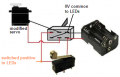
Hello, I'm trying to build a useless machine, and I need some help figuring out power supply and resistors. I have a Parallax R174 continuous rotation servo that is powered by 6 volts

http://www.acroname.com/robotics/parts/R174-CONT-RO-SERVO.html

I also have 6 RL5-G8045 LEDs

http://www.superbrightleds.com/more...een-led-45-degree-viewing-angle-8000-mcd/271/

I then have one DPDT switch and one SPDT lever switch and a 4 AA battery holder. Given that the servo runs on 6 volts though I'm wondering if I need a bigger battery holder. I also don't know how to figure out what kinds of resistors I need or how to arrange the LED array, as in series or parallel or maybe 2 series of 3 LEDs or some other such arrangement.

If anyone could help me figure out how to wire this stuff I would really appreciate it as I am very much a novice when it comes to electronics.

Jon
 

wayneh

Joined Sep 9, 2010
17,496
What are you trying to do? From what you've said so far, the easiest thing would be to throw everything in a box and go do something else. :p
 

mcgyvr

Joined Oct 15, 2009
5,394
Servos don't just run when you attach power to them.. You need a control pulse on the 3rd wire..

Also like wayne said you didn't tell us anything about what you want this useless machine to do.
 

Audioguru

Joined Dec 20, 2007
11,248
The LEDs need 3.5V so they will not light if you connect them in series.
Use Ohm's Law to calculate a series resistor for each LED so that its current is 20mA.
 

Audioguru

Joined Dec 20, 2007
11,248
I'm trying to build one of these... but one that lights up.
It is a box with an on-off switch on top. When you turn on the switch then the servo opens half the top of the box and an arm comes out and turns off the switch.

If the servo is 6 volts and the LEDS are 3.5 should I get a power source that puts out more than 6 volts?
4 alkaline battery cells in series make 6.4V when new, then quickly drop to 4.8V so the motor will run slower and LEDs will be dimmer. The battery voltage continues to drop as it wears out.
The 555 timer that controls the servo has a minimum supply of 4.5V.

The LEDs are about 3.5V so with a 6V supply the current-limiting resistor for each one has 6V - 3.5V= 2.5V. The datasheet for the LED shows that 30mA is maximum but its brightness is measured when its current is 20mA.
Ohm's Law calculates the resistor to be 2.5V/20mA= 125 ohms. 120 ohms is the nearest standard value. One resistor should be connected in series with each LED.
When the battery drops to 4.5V then the current in the LEDs is (4.5V - 3.5V)/120 ohms= 8.3mA which is dim.
 

Thread Starter

Helven_Ink

Joined Jan 31, 2012
10
The version of the design I'm looking to build says it doesn't need a 555 timer.

"Compukidmike was quick to point out that by modifying a continuous rotation servo (basically just using the the servo as a geared motor) and using the same switches it wouldn’t require ANY control circuitry.

Much simpler and just about any geared motor or a modified standard servo can be used. Start looking through your junk pile because Useless Machines have even been made from CD/DVD drives.

So you have a choice. Step 5 is the easy method."

But basically what you're saying is that I should run all the LEDs parallel with a 125 Ohm resistor on each one? What size should they be? I know there are different grades of the same Ohm resistor, like 1/2W and 1/4W or something like that?

I'm also wondering if I should go and get one of the 8 AA battery holders from radioshack. I would like to have plenty of power to make the LEDs bright and the servo strong. The servo I have has a speed adjustment screw on it, so I can slow it down or speed it up as I see fit... supposedly, but I'll worry about that later

So if I use an 8 AA battery holder, then they would produce 12.8 volts?
You still list the power supply as 6V when describing Ohm's law for the LEDs so should I assume 12V from an 8 AA power source? Also how does the 6V requirement for the servo factor into this?

Also, thank you for your help. :)
 

Thread Starter

Helven_Ink

Joined Jan 31, 2012
10
Basically what I want this machine to do is:
You flip the switch on the outside of the box, this powers up the servo and lights the LEDs. The servo has an arm attached to it that pushes open the box and flips the switch on the outside of the box which reverses the direction of the servo, pulling the arm back into the box until it trips a lever switch that opens the circuit, cutting off power to the servo and the LEDs.

According to what I've read, flipping the switch on the outside of the box should jolt the servo (with some adjustment) off the lever switch which then allows the circuit to close and powers everything up. When I first read about this machine, it seemed simple enough to build, and it seems like it still would be if not for the complicating factor of me trying to add LEDs into it. I imagine this is probably pretty easy for many of you guys to sort out, but I don't know very much about electronics. I'd like to learn, but it's difficult to get started without help.
 

Audioguru

Joined Dec 20, 2007
11,248
The version of the design I'm looking to build says it doesn't need a 555 timer.
Then why didn't you post the circuit instead of posting the Instructables project that shows 3 circuits with 555 drivers?

Compukidmike was quick to point out that by modifying a continuous rotation servo (basically just using the the servo as a geared motor) and using the same switches it wouldn’t require ANY control circuitry.
Then post the circuit and modifications needed for the servo.

Step 5 is the easy method.
Step 5 of what? Post it.

But basically what you're saying is that I should run all the LEDs parallel with a 125 Ohm resistor on each one?
No.
LEDs should NEVER be connected in parallel unless you measure the voltage of hundreds of them and select some that have exactly the same voltage. Their voltage is different for each LED.
Each LED needs its own series current-limiting resistor.

What size should they be? .... 1/2W and 1/4W or something like that?
The calculation for power in a resistor is simple: Voltage across it times the current in it, voltage across it squared divided by the resistance or the current in it squared times the resistance. The resistor will get extremely hot if it dissipates power at its rating so double its rating.

Simple Arithmatic Time:
1) 6V supply.
2) 20mA in each LED.
3) Each LED needs 3.5V.
Ohm's Law calculates the series current-limiting resistor to be 120 ohms.
Then the resistor has 6V - 3.5V= 2.5V across it. Then it dissipates 2.5V squared / 120 ohms= 0.052W. Doubled it is 0.1W so a 1/4W resistor is fine.

I'm also wondering if I should go and get one of the 8 AA battery holders from radioshack. I would like to have plenty of power to make the LEDs bright and the servo strong. The servo I have has a speed adjustment screw on it, so I can slow it down or speed it up as I see fit... supposedly, but I'll worry about that later.

So if I use an 8 AA battery holder, then they would produce 12.8 volts?
You still list the power supply as 6V when describing Ohm's law for the LEDs so should I assume 12V from an 8 AA power source? Also how does the 6V requirement for the servo factor into this?
8 battery cells in series require everything to be calculated again. Something must reduce the voltage to the servo and it will probably waste a lot of battery power making heat.
Maybe some LEDs can be connected in series.
 
Last edited:

Thread Starter

Helven_Ink

Joined Jan 31, 2012
10
Here is a link to step 5 of the instructable:
http://www.instructables.com/id/The-Most-Useless-Machine/step5/Wiring-Diagram/

It shows a wiring diagram for wiring the machine sans LEDs.I think that wiring up the circuit without LEDs would be pretty straightforward, but I don't understand how the addition of LEDs affects the circuit. Do I calculate what kind of resistor is necessary, stick one after each LED in series, with the LEDs being in series behind the servo?
 

Audioguru

Joined Dec 20, 2007
11,248
Instructables are designed by people who know NOTHING about electronics.
The sketch shows a servo with only 2 wires but all servos have 3 wires. The 3rd wire needs pulses to make the servo work. The Instructables project shows improvements that show 3 ways that a 555 oscillator can make a servo work.
 

Thread Starter

Helven_Ink

Joined Jan 31, 2012
10
There is a link in the step 5 portion of this instructable that shows how to modify a servo into just a geared motor, removing the control board and putting power straight to the motor, eliminating the need for a control device.
Perhaps it's not ideal, but it seems like it should work and plenty of people seem to think that it does. I don't need help modifying the servo, I just don't understand how the addition of LEDs will change the power requirements of the circuit as a whole.

Can I run the whole circuit off of the 6 volts from 4 AA battery holder?
Should I design the circuit in series to power first the servo, and then the LEDs? or maybe the LEDs and then the servo? Maybe I should run the circuit for the LEDs and the circuit for the servo parallel to each other?
With regards to resistors, you said I need 125 Ohms, is that per LED, or for the whole circuit? When I made an LED array a couple years ago, I had to use I think a 15 or 20 Ohm resistor after each LED and it worked just fine... until my cat knocked the thing off the shelf and destroyed the sculpture the LEDs were set into a couple months back... That array was just LEDs though. I don't know how the addition of the servo affects the circuit. Do I still treat the LEDs as if I am wiring them up by themselves? or does the servo change how the LEDs need to be hooked up? if so, can you help me to understand how?
 
Instructables are designed by people who know NOTHING about electronics.
The sketch shows a servo with only 2 wires but all servos have 3 wires. The 3rd wire needs pulses to make the servo work. The Instructables project shows improvements that show 3 ways that a 555 oscillator can make a servo work.
Audioguru: I guess 2 years in tech school studying electronics was a complete waste of my time. Glad you have such a positive opinion of us instructables authors!

If you took the time to actually read the instructable or Helven_Ink's posts, you would have noted that the 'servo' in question has had it's controller electronics gutted. It was modded to be a gear motor, hence no third wire.

Audioguru: if you need help, please contact me. I'll be releasing schematics, pcb pattern, and laser-cutting templates for version 2 of the machine very soon.

Adding LED's to the machine is very easy, they can be put in parallel with a gear motor. As for current limiting, about 50 ohms @ 3 volts works good for red and green LEDs. If you are going to use 6 volts then 80-100 ohms. Also it doesn't hurt to test things out on a bread-board to find the right value.

Blatant spam: We do have complete parts kits that include a printed circuit board and our machine comes with red and green LEDs that light up the 'actuator'.

http://frivolousengineering.com/

Cheers,
Brett
 
Last edited:

Audioguru

Joined Dec 20, 2007
11,248
Can I run the whole circuit off of the 6 volts from 4 AA battery holder?
I don't think a little servo draws much current. The circuit runs for only a couple of seconds so four AA alkaline battery cells will last a long time.

Should I design the circuit in series to power first the servo, and then the LEDs? or maybe the LEDs and then the servo? Maybe I should run the circuit for the LEDs and the circuit for the servo parallel to each other?
The servo and the LEDs operate from 6V. If they are in series then they won't work.

With regards to resistors, you said I need 125 Ohms, is that per LED, or for the whole circuit?
I calculated 125 ohms as a current-limiting resistor in series with each
LED. But nobody makes a 125 ohm resistor so I said to use 120 ohms which is a standard value. Then the current in each LED is 20.8mA which is bright.

When the servo runs it will dim the LEDs when the battery is almost dead.
With a fairly new battery then some LEDs and the servo will operate fine.
 

Thread Starter

Helven_Ink

Joined Jan 31, 2012
10
Alright, I think I understand how to wire this stuff up now. Thanks guys! I'll post back a bit later and let you know how it goes. :)
 

Thread Starter

Helven_Ink

Joined Jan 31, 2012
10
Okay, so I went and modified the servo and did a mock wiring for the servo, and it works great! I turn on the battery pack and the servo starts spinning, I flip the toggle switch and the servo reverses direction, I press down the lever switch and the circuit opens and the servo stops.

I'm assuming that I want to run the power for the LEDs off of the lever switch so that they come on when the lever switch closes, and turn off when the switch opens.

In order to run the LEDs parallel with the servo, should I just run a line to power the LEDs off of the third pin on the lever switch? (This being the pin that has the power wire going to the servo in the diagram.)
From there, all 6 LEDs are to be run in series... right? LED, resistor, LED, resistor, etc...?
 

Audioguru

Joined Dec 20, 2007
11,248
The lever switch turns on the positive supply to the servo. Use it to also turn on the positive supply to the LEDs. I show it on the sketch and also I show the 0V common connection for the LEDs.
 

Attachments

Thread Starter

Helven_Ink

Joined Jan 31, 2012
10
Thanks Audioguru. I'll have some more time to work on this later tonight, but I've got quite a bit to do with the box before I can put this thing together. :)
 
Top