Facebook
 Google
 GitHub
 Linkedin
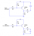
It's not as simple as you think. To design an interface circuit, you need schematics or specifications of the circuit driving the input, and the circuit being driven. We have neither. Nevertheless, try this.Nah dude dont give up. This has got to be a super simple circuit to make. I made you a pic but its really not important how the circuit is used. I just need a 12v pulse whenever I send it a ground pulse. Here is the pic (left out that the transistor pack has a ground going to it which will be used to ground the coil packs. And there are 2 wire bc of the 2 coil packs. This circuit will have to be produced twice.)
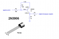
Thingmaker - I looked at your link, from what I can tell a PNP transistor will only let current through when a positive charge is applied? So this will not work for my application that I can see. Can you give me a diagram of how this would work?
I found something called a ground-gate transistor. Isint this something like I need. When ever it is grounded it completes the connection? Haven't found to much info on these.
Attachments
-
 8.8 KB Views: 69