Converting 4 negative signals to 4 postitive signals on 1 PCB

crutschow

Joined Mar 14, 2008
38,598
I guess the proper terminology is “trigger”. The switched negative lead is what “triggers” the coil packs to switch, but the new one’s require a positive trigger.
You still haven't properly defined what exactly the signal is for a "switched negative lead" or a "positive trigger".
You keep using those terms but they have no precise technical meaning in this context.
Until you do give us that, we can't give you a precise answer.
 
Last edited:

LowQCab

Joined Nov 6, 2012
5,101
By all means have at it,
after all, it's your Time and Money.

I prefer winning Races setting Records,
But I must suppose that some people don't really care about what actually works.

Please don't "Oil-Down" the Track during your learning phase.

I'll still help You out if You want to ask for more info.
.
.
.
 

Thread Starter

Jyrnes

Joined Oct 28, 2024
14
Still have properly defined what exactly the signal is for a "switched negative lead".
Basically the old style coil packs have 2 wires. One that is a 12v+ constant, then another that is the ground. The ground is pulsed from the ECU to fire the ignition coil. I am trying to turn this ground pulse into a 12v+ pulse.
Thank you.
 

BobTPH

Joined Jun 5, 2013
11,585
Yes this is true, I get what you are saying with the term signal. I guess the proper terminology is “trigger”. The switched negative lead is what “triggers” the coil packs to switch, but the new one’s require a positive trigger.
Thanks
Call them what you want, the question is whether they need to provide power or not. That has not been answered. If the thing coil you are trying to drive requires a significant current, the schematic you posted is nowhere near doing that.
 

BobTPH

Joined Jun 5, 2013
11,585
Basically the old style coil packs have 2 wires. One that is a 12v+ constant, then another that is the ground. The ground is pulsed from the ECU to fire the ignition coil. I am trying to turn this ground pulse into a 12v+ pulse.
Thank you.
And what does the new one have? Can you link a link to its specifications, or at least post a picture if it and any instructions that came with it?
 

Thread Starter

Jyrnes

Joined Oct 28, 2024
14
Call them what you want, the question is whether they need to provide power or not. That has not been answered. If the thing coil you are trying to drive requires a significant current, the schematic you posted is nowhere near doing that.
It doesn’t require much current, because it is just tells the coil when to fire. The coil is getting a constant 12v+ and ground. The trigger just tells it when to do so
 

Thread Starter

Jyrnes

Joined Oct 28, 2024
14
And what does the new one have? Can you link a link to its specifications, or at least post a picture if it and any instructions that came with it?
The new one is a 3 wire that has constant 12v+, constant ground, then the trigger wire that tells it when to fire.
 

MrChips

Joined Oct 2, 2009
34,974
Basically the old style coil packs have 2 wires. One that is a 12v+ constant, then another that is the ground. The ground is pulsed from the ECU to fire the ignition coil. I am trying to turn this ground pulse into a 12v+ pulse.
Thank you.
See, you're making the same mistake. You are using the wrong terminology.

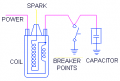
1735244208338.png

This is how a traditional ignition coil is wired.

Yes, the primary coil has two wires. One wire is connected to battery + terminal.
The other terminal is shorted to ground by breaker points.

If this is how a modern ECU works, the ECU has to short the terminal to ground. "The ground is pulsed" is not the way to say this.

Now, are the breaker points normally open or normally close? It has been many moons since I worked on a car with breaker points.

Edit: Breaker points are normally closed. Opening the points stops the current from flowing in the primary winding. The collapse of the magnetic field induces a current in the secondary winding which produces the high voltage spark. When I once fitted my car with electronic ignition, this was all reversed. The coil was grounded and the primary was fed with a +40V pulse.
 

BobTPH

Joined Jun 5, 2013
11,585
It doesn’t require much current, because it is just tells the coil when to fire. The coil is getting a constant 12v+ and ground. The trigger just tells it when to do so
That is not possible with only two wires. Both must carry all the current the coil requires.

The new coil, with three wires, might work that way.
 

Thread Starter

Jyrnes

Joined Oct 28, 2024
14
That is not possible with only two wires. Both must carry all the current the coil requires.

The new coil, with three wires, might work that way.
I’m very confident with what I am doing. Do you see any problems with my wiring diagram other than the current being low? Would this provide the 12v positive that I am looking for?
Thank you.
 

Thread Starter

Jyrnes

Joined Oct 28, 2024
14
H
That is not possible with only two wires. Both must carry all the current the coil requires.

The new coil, with three wires, might work that way.
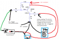
I'm having some trouble with Ron's board that I attached to the beginning of this thread. The output reads about 7 volts at all times as soon as the powerprobe is connected to the circuit, causing the coil to continuously fire, I would like this to be at 0v. Once I hit the negative switch on the power probe, voltage goes up to 12v which is what I want. What needs to change on the board to make it work as I intended if you could help.

I drew up how I was testing the circuit if this helps. Thank you
 

Attachments

Thread Starter

Jyrnes

Joined Oct 28, 2024
14
I
See, you're making the same mistake. You are using the wrong terminology.

View attachment 338982

This is how a traditional ignition coil is wired.

Yes, the primary coil has two wires. One wire is connected to battery + terminal.
The other terminal is shorted to ground by breaker points.

If this is how a modern ECU works, the ECU has to short the terminal to ground. "The ground is pulsed" is not the way to say this.

Now, are the breaker points normally open or normally close? It has been many moons since I worked on a car with breaker points.

Edit: Breaker points are normally closed. Opening the points stops the current from flowing in the primary winding. The collapse of the magnetic field induces a current in the secondary winding which produces the high voltage spark. When I once fitted my car with electronic ignition, this was all reversed. The coil was grounded and the primary was fed with a +40V pulse.
I didn't meant to sound harsh with my last response to this. Coil on plug is a completely different set up than this. Coil on plug basically has a ignition coil for each individual cylinder. Older style ignition setups use one coil for all the cylinders in the engine.

Coil on plug setups have 3 wires going to them. 12v+, 12v-, and the ECU shorts to positive to tell the coil when to fire.

Hopefully this clears some things up.
 

LowQCab

Joined Nov 6, 2012
5,101
"" and the ECU shorts to positive to tell the coil when to fire. ""

On some Coils this is true,
on some Coils the ECU holds the Coil "On" for as long as the signal is positive,
this is called "Dwell-Time",
while on other Coil designs the Dwell is automatically calculated inside the Coil.

These same 2 scenarios may apply to a "Switched-Ground" arrangement also.

That's 4 different operating modes that are possible,
what type or mode did your Engine come with ?,
and what method was used with the Coils that You intend to use ?

Why are You taking such a risk when You are not positive what the outcome will be ?

What is the supposed advantage of changing the Coils ?
.
.
.
 
Top