Control actuator via Potentiometer?

Thread Starter

Gordonov

Joined Mar 19, 2012
17
Hello all,

As the title says, I'm attempting to control a linear 12V actuator with a potentiometer (or two!)
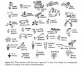
Attached is a diagram of how I plan to wire it up.
Can anyone give me some pointers if what I am doing is;

a) Stupid
b) Ridiculous
c) Insane

Or otherwise give me their ringing endorsement?

Essentially, I am wanting to convert small movement (input to Pot A) to big movement (Actuator), and have the actuator stop when the movement stops. To explain it another way, imagine Pot A is set in a position, X, and this is the fully retracted position for the actuator. When I dial Pot A upwards, I want the actuator to extend proportional to the speed of the input, and stop if the input stops (even if it stopped halfway or at some random point). If I reverse the input to Pot A, I then want the actuator to retract (also proportional to speed).

I thought to achieve this via a 2 x Pot, 1 x op-amp setup - a pot to control input, a 'feedback' pot, and the op-amp as in the attached picture.

Any thoughts??

Cheers
 

Attachments

MikeML

Joined Oct 2, 2009
5,444
I recently bought a 12Vdc linear actuator that had a built-in linear position feedback potentiometer (10K).

On your null seeking controller. You will need two opamps/comparators configured such that there is a dead-band between where the actuator runs in and runs out, otherwise it will constantly hunt. The need for doing this is explained in this old forum posting...

Another idea is to hook your control pot (joystick?) to the A/D input of an Arduino, hook the feedback pot to a second A/D input, and do the null seeking in software. You could use the Arduino's PWM output to control motor speed, and a relay to change actuator direction. I did that with my linear actuator..
 
Last edited:

#12

Joined Nov 30, 2010
18,224
I made a stab at interpreting your words and it came out like this.
It's nowhere near finished, but it shows how to get a velocity of changing voltage to create a proportional current to drive the actuator quickly or slowly. It also has a circuit that detects any motion at all and that signal allows or interrupts power to the actuator.

It might or might not resemble what you want, but it's a start.
 

Attachments

Thread Starter

Gordonov

Joined Mar 19, 2012
17
MikeML,

Thanks for your feedback - I read through that forum post but I'm afraid my understanding of electrical circuits is pretty limited so I had difficulty making heads or tails of the conversation...so you're saying I need an additional op-amp in the circuit...any chance you could indicate where I should be wiring it in to make it work? I understand there needs to be a 'dead zone' otherwise the actuator will be continually mobile, I'm just not sure how to implement it on a practical level...

#12,

Thanks for the diagram, that's intense haha...as I said to Mike, my understanding of electrical circuits is very limited so I'm trying to make sense of it - is that 7 x op-amps? I understand the diode symbols and the resistors, except how come some are 'R1, R2' etc, while others have resistance values specified?
Also, where does the 5V+ DC come from? I assume the +15V and -15V are from the power supply? What are the ends that terminate in small triangles?
Thanks for your patience and please excuse my ignorance!

Cheers
 

#12

Joined Nov 30, 2010
18,224
The little triangles pointing down are ground symbols. The 5 volts is something you make from the 15 volt supply, just to make a voltage that is rather stable regardless of whatever else goes on with switching and current changes. Some of the resistors don't have values because I didn't do the math to find the values. After all, who was to know if you'd be back here today?

Anyway, the basic premise is that the velocity of the pot change can be measured and amplified and converted into a proportional current drive for the actuator, and the fact that the pot is moving at all can be detected, amplified, and used for an on-off switch. This first drawing is only covering one direction of movement. The basic building blocks are mostly there. They just have to be arranged to do what you want. For instance, doing a bidirectional controller would involve adding an amplifier after the motion detector and not putting a precision rectifier in so the information about whether it was moving one direction or the other would not be lost. The movement detector information would be sent to an H-bridge so it can reverse the actuator movement. Just, I'm not good with H-bridges.:oops:

So, this is the analog way to do it. The microprocessor method would use a lot less parts. The big problem in my mind is about you defining what you want. How much movement? How fast? Those things define the unlabeled resistors and capacitors. You can have this thing slap the actuator against the limit switch in a few milliseconds or take all day to get there. Big problem: You don't know how to do trial and error testing to set the time constants and amplification factors, and I can't do that without building this whole circuit and having the actuator on my work bench for a few days...and I'm not going to do that. So, we're at the point where somebody (you) can have an idea, but it's never going to get built unless you're willing to pay a design engineer to build it.
 
Last edited:

Thread Starter

Gordonov

Joined Mar 19, 2012
17
#12,

No problem about the resistor values haha...I was just curious in case they were a different kind or something.
At this stage the level of complication is making me consider the Arduino approach. I've never used them before but I understand there's a lot of information about them out there.
What I am really attempting to do with it to have the extension of the actuator represent the movement of a finger. So if my finger was straight, the actuator would be at its closed limit...if I were to move my finger downwards, the actuator would extend at a proportional speed to my finger...once my finger has touched the palm of my hand, the actuator would be at its extension limit. If I was to stop my finger at any point in the movement, the actuator would also stop. I had the idea of connecting the tip of my finger via cable to a control pot (that was spring-loaded to be fully resistive if my finger was straight (and hence the actuator would be at its closed limit) - then by moving my finger (and hence the cable, pulling open the pot at the same time), then I would be controlling it this way. I have nil idea how to implement this idea with an Arduino but I guess the first step is buy one and start researching.
 

#12

Joined Nov 30, 2010
18,224
What you're describing now is nothing more than an antenna rotator, except they always move at the same speed...as fast as they can go...to get to the next position you stopped at. That doesn't require a computer! You're just making this more complicated than it needs to be.
 

Thread Starter

Gordonov

Joined Mar 19, 2012
17
Yeah I had a suspicion I was making it too complicated.
Would something like this work, with the two switches controlling forward and reverse?
Oh, and the power supply being 12V instead of 6V.

Cheers
 

Attachments

#12

Joined Nov 30, 2010
18,224
Yeahbut...you should look at an antenna rotator from Radio Shack. The way that works is that you turn a knob to the position you want and the rotator runs until a pot in the motor head arrives at the same place as where you set the first pot. That eliminates holding the button and judging when you have arrived at the right position.
 

Thread Starter

Gordonov

Joined Mar 19, 2012
17
Unfortunately we don't have Radio Shack in Brisbane, Australia...there's one in NSW but it doesn't appear to stock any antenna rotators.
I tried a few searches for antenna rotators / antenna rotator controllers but didn't turn up much of substance from any other supplier. I could order it in but that would take a while.
 

Thread Starter

Gordonov

Joined Mar 19, 2012
17
Guys,

I tried to breadboard the schematic in Post #10 up...this is the first time I've even used a breadboard if I'm honest.

I took a photo of it and highlighted the paths for easier reading - for reasons unknown to me, when I wire it up, apply power and try the switches, the actuator does nothing, it just sits there.

My lack of electronics knowledge defeats me here so I'm hoping someone can tell me where I've gone wrong. It's probably obvious to anyone but me!

The switches being used are 4-prong momentary tactiles, I removed them (and the actuator cables) for better visibility.

Cheers!
 

Thread Starter

Gordonov

Joined Mar 19, 2012
17
Bump, anyone??
This is the first time I've used a motor driver and I still don't fully understand it. Should I be using momentary switches or something else?
 
Top