Continuous auto reverse DC motor

Thread Starter

Mogey

Joined Oct 8, 2012
4
New to all this. My first post.
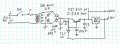
I have a 120VAC to 24V Transformer that I want to power a 24VDC motor.
I want this motor to have a main power on/off switch, but once it is turned on I want it to run in one direction until it hits a limit, then reverse automatically and return to the other limit, and then automatically reverse again continuously until I turn off the power. What switches and relays do I need and how do I connect them?
 

wayneh

Joined Sep 9, 2010
17,496
You need to define how the "limit" is detected. Number of rotations? Linear travel of something the motor is moving?

This would be a bit easier if you could simply reverse the polarity to the motor without a brief stop in between. But some motors cannot tolerate that and it gets worse if there's a flywheel or other moving mass to stop and reverse. Do you need a pause?

How big is the motor, in terms of current (amps) rating?
 

cork_ie

Joined Oct 8, 2011
428
Sounds very similar to a windscreen wiper motor setup.
Maybe you could adapt a wiper linkage to suit your purpose.That way the motor can continue to rotate in one direction but actually reverse the direction of rotation on the linkage with each cycle mechanically.

I know that Volkswagen are now using H Bridge motors for the windscreen wipers in some of their modern cars which does exactly as you describe. The only problem is that they are all 12 Volt not 24.

If you can give us a little more information perhaps I can help.
 

Thread Starter

Mogey

Joined Oct 8, 2012
4
You need to define how the "limit" is detected. Number of rotations? Linear travel of something the motor is moving?

This would be a bit easier if you could simply reverse the polarity to the motor without a brief stop in between. But some motors cannot tolerate that and it gets worse if there's a flywheel or other moving mass to stop and reverse. Do you need a pause?

How big is the motor, in terms of current (amps) rating?
Yes, linear travel of something the motor is moving, to be detected by some sort of switch (which i need help with), at both ends of travel. Motor is 24V .4 amps. I need to know what type of switches would work best for detecting limit and allow for automatic reversing of polarity either by other switches or relays (which i also need help with)
 

Thread Starter

Mogey

Joined Oct 8, 2012
4
Here is what I am trying to accomplish...
I am trying to get a motor to power what I'll call a mini elevator to go up and down continuously from top to bottom while at the same time another motor will power that "elevator" shaft back and forth horizontally also continuously side to side. The "limits" of both movements will be one all the way up and all the way down, and two all the way left and all the way right. I have two 24V motors but need to know what kind of switches to detect limits and what kind of switches or relays to reverse polarity. Motor is 24V .4 amps
 

Thread Starter

Mogey

Joined Oct 8, 2012
4
Sounds very similar to a windscreen wiper motor setup.
Maybe you could adapt a wiper linkage to suit your purpose.That way the motor can continue to rotate in one direction but actually reverse the direction of rotation on the linkage with each cycle mechanically.

I know that Volkswagen are now using H Bridge motors for the windscreen wipers in some of their modern cars which does exactly as you describe. The only problem is that they are all 12 Volt not 24.

If you can give us a little more information perhaps I can help.

I love this suggestion but my length of travel needed is about 30 inches
The cam would have to be fairly long to achieve this
 

wayneh

Joined Sep 9, 2010
17,496
Well there are all kinds of options. Roller limit switches. Reed switches (with a magnet on the "car"). IR beam interrupt (like a garage door). There must be more but I'm drawing a blank.

I'd probably lean towards the latter, since it doesn't require any mechanical horsing around.
 

John P

Joined Oct 14, 2008
2,025
There are some pretty robust switches out there, capable of taking some battering. Or you can use a much smaller switch, but just be sure that the moving part is able to travel past it, rather than having an arrangement where if the carriage doesn't stop, it will crush the switch. I say mechanical switches because they're more foolproof than light beams. I had an incident years ago when we demo'd a device for a visiting VIP and in his honor, we opened the blinds which we never took the trouble with usually, and the daylight shone on our optical limit switches and prevented them from acting as switches. It was embarrassing.

You can wire this with one relay per axis, if it's a 3-pole relay. One switch would turn the relay on, then the other would turn it off again, and the relay would set the direction of motor travel. But that issue of reversing a moving motor is a concern--it would be better to stop the motor before starting up in the opposite direction.
 
I did something similar (It would work for exactly what you describe I think). I used a CD4013 Flip flop, that was triggered by hall senders on each end (Magnet mounted to car would need to get about an 1/8" from hall sender at each end of your "Track"). I used the output of the CD4013 hooked up to both sides of an LM393 and 2 equal resisters (I used 2 3.3K's) to make a voltage divider for the reference voltage on both sides of the LM393 (So it makes a reference voltage half of your supply voltage). I just switched the "+" and "-" wires on either channel of the LM393 so the outputs alternated as the CD4013 went high or low with each trigger. I used those 2 LM393 outputs to drive two relays. Wire both relays "N.O." Contacts to voltage positive, and both relays "N.C." Contacts to voltage negative/ground. The common pin from each relay will go to your two motor wires. When one relay gets activated, the motor will go one way, when that one is deactivated, and the other activated by the hall sender, the motor will go the other way. Let me know if that makes sense. I could probably provide a diagram.
 

Audioguru

Joined Dec 20, 2007
11,248
You said that you have a transformer with a 24V output. Isn't that AC?
But you said your motor is DC.
Then you need to convert 24VAC to 24VDC. A rectifier will do it but it will make the motor hum and buzz loudly. If you filter the hum with a large capacitor then the DC voltage will be too high.
 

Bernard

Joined Aug 7, 2008
5,784
Yes it is. Now I need 7 more words to post. If it were me, the filtered & rectified AC excess 7 Vs would be dropped with 10W, 10 ohm resistor. The benefit is reduced starting surge motor current. A 12 V reg. would be used for logic & relays.
 
Last edited:
Top