Configuring input to voltage follower taking external signal

Thread Starter

PeteHL

Joined Dec 17, 2014
475
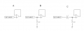
The first stage in my design of a line level audio signal processing circuit is a non-inverting (op amp) voltage follower. The signal at input might be for example one channel of output of a CD player.

The voltage follower might be simply configured as shown at A in my attached diagram. Following the principle of less is better, this might be very acceptable as input impedance of the non-inverting input terminal of the follower is very high.

However, as shown at B in the diagram, often times the follower is shown with a resistor connected from the non-inverting input terminal of the op amp to reference potential. I've seen resistance of this resistor specified as 100 k Ohm. Why would this resistor be included?

Finally, a further embellishment as shown at C in the diagram, is a capacitor connected between the input signal jack and the non-inverting input terminal of the op amp. What this is for I would think is to block direct current where the external equipment and the circuit including the voltage follower have differing reference potential. Is the capacitor necessary for my circuit?

Thanks for your input,
Pete

BUFFER.png
 

Attachments

#12

Joined Nov 30, 2010
18,224
Is the capacitor necessary for my circuit?
Does your input have any DC in it?
I've seen resistance of this resistor specified as 100 k Ohm. Why would this resistor be included?
All op-amps have some tiny amount of current flowing at their inputs. If there is no path to ground, the current will load up a voltage on the input pin and the amplifier stops working. Fairly often the input signal has no DC and it also has a resistance to ground. The input device provides the necessary current path. When this is not true, you must provide a DC path to ground. The ohms of the ground path depend very much on which amplifier chip you use.
 
You can also look here: http://www.daenotes.com/electronics...al-amplifier-bias-current-compensation-method which is a method of bias current compensation.

Consumer pre-amps are riddled with capacitors.

Mine, a consumer/professional variety and has a -3db frequency out to 100 kHz. There are two amplifier outputs. One is DC-100 kHz and the other is 0.5 Hz to 100 kHz. The separate amp has an inherent DC filter. It also has a filter at about 40 kHz and an RF filter.

A large resistor does contribute thermal noise.

Real professional equipment used balanced XLR inputs with balanced inputs. read here: https://en.wikipedia.org/wiki/Line_level for a line out description and balanced https://en.wikipedia.org/wiki/Balanced_line connections.
 

Thread Starter

PeteHL

Joined Dec 17, 2014
475
Does your input have any DC in it?

All op-amps have some tiny amount of current flowing at their inputs. If there is no path to ground, the current will load up a voltage on the input pin and the amplifier stops working. Fairly often the input signal has no DC and it also has a resistance to ground. The input device provides the necessary current path. When this is not true, you must provide a DC path to ground. The ohms of the ground path depend very much on which amplifier chip you use.
Thanks for explaining the function of the resistor.

As the input would be from some commercial signal source such as CD player, tuner, etc., I wouldn't expect that such a source would have a DC voltage. But I was thinking that possibly it would be problematic, if DC blocking with a capacitor isn't included, to make a zero resistance connection between the reference voltages of each equipment. For example connecting output to input with phono cable, the shield of the cable connects terminals at reference potential of the two devices and the two reference potentials are not of equal voltage.
 
Last edited:

#12

Joined Nov 30, 2010
18,224
If this and if that, but the safe way is to use a capacitor in series and a resistor to ground. The resistance to ground depends on the amplifier chip you use for its maximum resistance but the signal source defines the lower limit. If your source is supposed to drive an 8 ohm speaker, 800 ohms for the resistance to ground would be just fine with the driver, but a waste of power the chip doesn't need and would require a lot bigger capacitor than if you used 10,000 ohms. Most modern chips will be happy with 100,000 ohms to ground. For that you calculate the capacitor as C = 1/(2 x Pi x lowest frequency in Hz x R) It usually comes out as a few tenths of a uf.

Having established a DC blocking capacitor and an independent path to ground, it doesn't matter what you plug in for the source of signal. It can be clean of DC, It can be a bridged amplifier, It can be a signal centered at half the most positive voltage available...and your amplifier chip won't care because it is properly biased completely separate from the source.
 

Thread Starter

PeteHL

Joined Dec 17, 2014
475
If this and if that, but the safe way is to use a capacitor in series and a resistor to ground. The resistance to ground depends on the amplifier chip you use for its maximum resistance but the signal source defines the lower limit. If your source is supposed to drive an 8 ohm speaker, 800 ohms for the resistance to ground would be just fine with the driver, but a waste of power the chip doesn't need and would require a lot bigger capacitor than if you used 10,000 ohms. Most modern chips will be happy with 100,000 ohms to ground. For that you calculate the capacitor as C = 1/(2 x Pi x lowest frequency in Hz x R) It usually comes out as a few tenths of a uf.

Having established a DC blocking capacitor and an independent path to ground, it doesn't matter what you plug in for the source of signal. It can be clean of DC, It can be a bridged amplifier, It can be a signal centered at half the most positive voltage available...and your amplifier chip won't care because it is properly biased completely separate from the source.
Thanks very much for the excellent design guidelines!
 

#12

Joined Nov 30, 2010
18,224
Thanks very much for the excellent design guidelines!
In the end, money is a factor. If you know every possible signal source and what it's doing, you can often enough leave out the capacitor or design the amplifier stage to accommodate whatever the input is going to be. If you don't know what every random stranger is going to plug into your amplifier...you build it bulletproof with drawing "C".
 
Top