configuring an LM35 temperature sensor to switch on.

Thread Starter

ali8tor

Joined May 29, 2012
43
Hi all
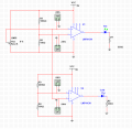
im currently working on a small project and i find my self stuck in terms of configuring an LM35 temperature sensor to switch on at a set temperature, for example i would like an led to turn on when the temperatures 36 degrees and also turn on when the temperature is 20 degrees otherwise off. I plan on doing this through a comparator circuit but cant find a method of setting it up?

any help would be appreciated thanks
 

Dodgydave

Joined Jun 22, 2012
11,285
you could use a LM3914 in dot mode, and set the lower limit to 200mV, and upper limit to 360mV, then the leds will light up at 20C, and 36C.

or use a dual op amp comparator and set the limits as above.
 

DickCappels

Joined Aug 21, 2008
10,152
<some text removed for clarity>

I plan on doing this through a comparator circuit but cant find a method of setting it up?˙

any help would be appreciated thanks
Sorry, I was telling you something you already knew. I did not catch the true question in your post until now.

There might be a more clever approach but my first take on it would be to use two comparators, one set to threshold and a set-reset flip-flop (you could get by with one comparator and the correct hysteresis but the two comparators are straight-forward and you don't have to recalculate anything to change the settings.).

The LM35's output is 0 mv + 10 mv/°C, so you could set the 20° threshold at 200 mv and the 36° threshold at 360 mv -you might want to use pots for this if fine-tuning or any kind is needed.

If you want the LED to be on whenever the temperature is 30° or higher or when the temperature is 20° or lower you can use a window comparator like the one below (use the LM35 output instead of the pot).


The circuit above is explained at the page upon which it was found: http://www.bristolwatch.com/ele/vc.htm[/QUOTE]
 

#12

Joined Nov 30, 2010
18,224
That's a comparator chip. It is called, "open collector output". It needs RL to power the output (as shown in the drawing of post #4). That RL must carry the current of the LEDs which are attached to the output. This is a form of, "or" gate. If either one comparator or the other has a low output, the final output voltage is nearly zero. When both comparators are at a "high" output, no current from RL is dumped to ground through the comparators, so it is available to run an LED.

There are many ways to configure how many LEDs and when they are on. The decision of when to switch has been demonstrated with the drawing. Exactly how you want the LEDs to work seems to be still open to interpretation.
 

Thread Starter

ali8tor

Joined May 29, 2012
43
Hi

the window compactor would work great but the only problem is when, Vin is equal to or greater then UTP the led is on. where i need my circuit to be off when Vin is if greater then UTP. is there any way around this?

thanks
 

MikeML

Joined Oct 2, 2009
5,444
Here is how to set up a window comparator so that the LED turns on when V(LM35)<200mV OR V(LM35) >360mV. In the sim, a voltage source is used to represent the LM35 [V(lm35)= green]. The two trip point voltages are shown[blue & violet], as is the current through the LED [red] as a function of the LM35 voltage.

Personally, I would use two different color LEDs (or a bi-color one) to indicate high and low, rather than just one LED. Color would indicate too cold or too hot. With a little logic, you could use Red to indicate too hot, Amber (Red+Green) to indicate too cold, and Green to indicate just right,

This circuit uses the open-collector type of i.c. comparators U1 and U2, like the LM339. The battery is used to show a non-precision voltage supply that can vary by -25%. The LED, U1 and U2 can be fed directly from the non-precision voltage source with no consequence, except the LED will get slightly dimmer as the battery discharges.

The two trip points V(high) and V(low) must be very stable, so cannot just be a resistive divider taken directly from the battery, otherwise they will shift as the battery discharges. I show the voltages as being derived from a precision current source such as a LM334, or you could use a precision voltage reference IC with a three-high resistive voltage divider.
 

Attachments

Last edited:

MikeML

Joined Oct 2, 2009
5,444
Hi

the window compactor would work great but the only problem is when, Vin is equal to or greater then UTP the led is on. where i need my circuit to be off when Vin is if greater then UTP. is there any way around this?

thanks
I just read this after I posted the above. Your specs are ambiguous.

In post 1 you seem to be asking for a single led to be on <20deg and >36deg?
In post 6 you seem to be asking for a single led to be on if >20deg and <36deg?
 
Last edited:

Thread Starter

ali8tor

Joined May 29, 2012
43
Ive made this circuit which turns on when the temperature is 39 degrees and 12 degrees this circuit works well but my only problem is making it on breadboard it doesn't work i've checked the circuit and it's fairly simple any solutions?
 

Attachments

Dodgydave

Joined Jun 22, 2012
11,285
you need to use a ref zener for stablility on the ref pins,
show pics of your breadboard,you probably made an error somewhere..
 
Top