component recomendation for converting analog sequencer into MCU based

Thread Starter

yef smith

Joined Aug 2, 2020
856
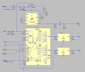
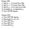
Hello ,I got this good QORVO manual shown below it uses a combination of regulators and a comporator.
all the component there are analog
LT1716 -analog comparator
LTC1261LCS8-4 - negative generator
LT1761-BYP- analog regulator
Could you reccomend me names of similar components which could do the same method using a microcontroller?
Thanks.


https://www.qorvo.com/products/d/da007774
https://www.analog.com/en/resources/technical-articles/power-supply-sequencing-simplified.html
https://www.minicircuits.com/pdfs/PMA5-83-2W-D+.pdf
https://www.qorvo.com/products/d/da007774

1712916891380.png
 

Attachments

Last edited:

Irving

Joined Jan 30, 2016
4,087
but i was told tht using DC-DC is too noisy for ampliyier.
Who said that?

Easy enough to control inputs to linear regulators if preferred though less energy efficient. A novel solution is to use a DRV8876 motor driver in its dual independent switch mode. This gives logic control of the output voltages and built-in current sensing for the 12v rail. In the circuit below a standard ICL7660 negative voltage generator is used with an opamp to track a +ve input voltage from the MCU's DAC output and provide a matching -ve bias voltage to the power amp. This allows adjustment of the bias to set the 400mA input current on the 12v rail as per the amp's data sheet. The current sense is provided by the DRV8876 and can be read as a voltage, where 2v = 400mA.

There are, of course, many high-side, logic controlled switches, some with current sensing, but the DRV8876 incorporates two switches and current sensing and, given its popularity as a motor driver, is very cheap by comparison.

1713024095062.png
 

Thread Starter

yef smith

Joined Aug 2, 2020
856
Hello Irving,how does the sequencing is being performed with DRV8876? In microcontroller i use GPIO periphery.
Also regarding the current sensing,i need two pins to measure the current ,where as in the plot there is only one pin.
How the current sensing is being performed on the amplifier?
Thanks.
 
Last edited:

Irving

Joined Jan 30, 2016
4,087
BIAS_ON, at the top, sets your -2v VG1 bias setting. A voltage here of 0 - +4v will produce a bias voltage of 0 to -4v at -BIAS (-VG1). Ideally produced by MCU's DAC. Alternately you can use a PWM output though will need additional filtering to be smooth enough .

Initial sequence, start at +2v (VG1 = -2v). Isense is the input to your MCU's ADC. It is 2v for 400mA

See the inputs 5v_ON and 12v_ON, these come from your MCU, all you need to do is raise them to logic 1 at the required time. So sequence 5_ON (VG2) then 12v_ON, reverse for turn off.

Full sequence::
C-like:
//experimental
//turn on
Set turn_Off_Req = 0
Set BIAS_ON at 2v
small_delay
Set 5V_ON to 1
small_delay
Set 12v_ON to 1
small_delay
Turn on RF //(not part of this circuit)
small_delay
While (true)
  iSense = 200 * analogRead(IsenseInput) //result in mA
  if Isense > 400 //may need tweaking up to prevent 'hunting'
     decrease BIAS_ON by 0.1v (or 1 count if PWM)
  else If Isense < 398 //may need tweaking down to prevent 'hunting'
     increase BIAS_ON by 0.1v (or 1 count if PWM)
  endif
  if(turn_Off_Req == 1)
    break
  short_delay //allow Isense to settle
Wend

// turn off requested
Turn_off_RF  //(not part of this circuit)
small_delay
Set BIAS_ON at 2v
small_delay
Set 5V_ON to 0
small_delay
Set 12v_ON to 0
small_delay
Set BIAS_ON to 0
 

Thread Starter

yef smith

Joined Aug 2, 2020
856
Hello Irving, a very serios problem i have is producing -2V with 4mA in G1.
Could you give an intuition regarding how this circuit works?

I made another circuit shown in the end but i get -2V at 400mA which is very bad,putting resistor ruins totally the -2V .

1718994022264.png

1718994375579.png

1718994456182.png
 
Top