Completing a schematic (solved)

Thread Starter

metermannd

Joined Oct 25, 2020
472
So I recently got a wild hair to get my hands on the various circuit boards that went to a piece of chip foundry equipment which boards I used to service back in the '90s, and I have managed to get a decent number of them figured out. There are two boards that are proving elusive.

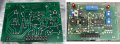
This one is a heater control board (on the rare occasion one turns up, the price asked tends to be in the 'highway robbery' range - and for a board that is based on a pair of 555 ICs??)

I managed to find a couple decent pictures of this board, but there are a few traces that disappear underneath parts that keep me from completing the schematic...

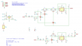
Attached are the schematic thus far and a composite picture of the component / solder sides. One correction: U4 on the board picture is a typo - it should be VR1 as on the partial schematic.

This board has two different timers: R14 (on left) is to set the duty cycle when output D6 is active.

R15 and R16 (right) are for output D5, the 'preheat' allowing adjustment of the duty cycle when output D5 is inactive, and the 'run' for when the output is active.

There are only six loose ends to be tied up on the drawing... hopefully someone who's familiar with the 555 can help?
 

Attachments

MisterBill2

Joined Jan 23, 2018
27,187
To follow nice brad traces like the ones in the pictures, when they go under an IC, since they may connect to a pin, just use your multimeter OHMS function and two sharp probes. On pin to poke thru the solder mask and the other to probe the solder at the pins, and see which one has a direct connection. It is a cheating trick that works.
 

atferrari

Joined Jan 6, 2004
5,001
Have you ever thought about measuring continuity with a simple multimeter? It is always a good idea to start by measuring with respect to the common and then with respect to Vcc, all pins of all ICs in an orderly numeric sequence.

Just by following that idea I managed to reverse engineering the complete main board of an Epson printer.

In Spanish (leave the translation to you) I use to say: más paciencia que ciencia.
 

nsaspook

Joined Aug 27, 2009
16,252
So I recently got a wild hair to get my hands on the various circuit boards that went to a piece of chip foundry equipment which boards I used to service back in the '90s, and I have managed to get a decent number of them figured out. There are two boards that are proving elusive.
Wow, old FSI boards. What ancient fab did those come from? What's the tool model name, Mercury?
 

Thread Starter

metermannd

Joined Oct 25, 2020
472
MisterBill2, atferrari: I do not physically have the board in my possession - these go for $250 and up when they come available.

Otherwise, yes, I would have reached for the DMM and measured them out.
 
Last edited:

Thread Starter

metermannd

Joined Oct 25, 2020
472
nsaspook: Just a couple pictures I scared up from some determined searching... afaik these came from the Saturn system.

The company I work for produced the majority of the boards for the Saturn, and at least the 'motherboard' for the Mercury (the one with a ton of 50-pin ribbon cable connectors and a sea of test points).

Seems the boards for the Saturn were split between two vendors, and the Heater board above was one of those assigned to the other vendor.
 

nsaspook

Joined Aug 27, 2009
16,252
nsaspook: Just a couple pictures I scared up from some determined searching... afaik these came from the Saturn system.

The company I work for produced the majority of the boards for the Saturn, and at least the 'motherboard' for the Mercury (the one with a ton of 50-pin ribbon cable connectors and a sea of test points).

Seems the boards for the Saturn were split between two vendors, and the Heater board above was one of those assigned to the other vendor.
If it was Mercury I might be able to get some board info. No SATURN and NEPTUNE here but we do have TEL systems, so I will ask those guys if they have anything.
 

Thread Starter

metermannd

Joined Oct 25, 2020
472
I remember working on the occasional Neptune board (they used the much smaller 1200 Process Controller and a correspondingly smaller interface board, but those were far and few in between)...

I'm mainly interested in recreating the schematics of the assemblies throughout the Saturn system - this -25 Heater board is one of a few boards I still need to chase down. (others: -09 CPU, -65 Autofill, -19 2800 P/S, Flow Control, etc).

If the Mercury used the same tub as the Saturn, the tach (290036-400) would be another one. Optical fork and a 5-pin jack.
 

nsaspook

Joined Aug 27, 2009
16,252
I remember working on the occasional Neptune board (they used the much smaller 1200 Process Controller and a correspondingly smaller interface board, but those were far and few in between)...

I'm mainly interested in recreating the schematics of the assemblies throughout the Saturn system - this -25 Heater board is one of a few boards I still need to chase down. (others: -09 CPU, -65 Autofill, -19 2800 P/S, Flow Control, etc).

If the Mercury used the same tub as the Saturn, the tach (290036-400) would be another one. Optical fork and a 5-pin jack.
Asked around but got nothing.
 

MisterBill2

Joined Jan 23, 2018
27,187
OK, and "sorry about that" as well. I had guessed that you had a board in hand. Guessed wrong. It is a good technique, but only if the PCB is in hand.
 

Thread Starter

metermannd

Joined Oct 25, 2020
472
Misterbill2: Not a problem. :)

If the board is pretty straightforward or sufficiently repetitive, it's not that hard to reverse-engineer by picture.
(at least the bulk of it anyway)
 

Thread Starter

metermannd

Joined Oct 25, 2020
472
An updated schematic:
I eventually determined that two loose ends that were obscured by the regulator had to be connected.
I also redrew the other half to be more consistent in its layout; hope it helps make the remaining loose ends a bit clearer.
 

Attachments

Thread Starter

metermannd

Joined Oct 25, 2020
472
Momentarily flush with disposable income, so I ended up ordering one of these (managed to track down one at a relatively reasonable price).
We'll see what the final answer is in a few weeks.
 

MisterBill2

Joined Jan 23, 2018
27,187
THAT is a well organized , easy to follow and understand, drawing. Thanks for sharing it with us.
It can also serve as a style reference for folks who need to see what an easy to follow drawing can be.
 

Thread Starter

metermannd

Joined Oct 25, 2020
472
Thanks. I may have to go back through the board and rebuild the netlist, now that I have an actual board in hand.

I don't quite follow what the purpose of R2 is, as it's basically across +12 and ground, unless it's there to provide a minimum level of load for the regulator on the board? The line 'Blnkt Heater' (and the +12) goes to a large bolt-on solid state relay.
 

MisterBill2

Joined Jan 23, 2018
27,187
Actually, Not only R2 to common, could it be intended for sourcing to U3A and U3B?? It does not seem quite right that those two sources for the duty cycle control are fed from the output line. If R2 instead connected to pins #1 and #4, instead of the line from U2, pin#3, I think that would make more sense.
 

Thread Starter

metermannd

Joined Oct 25, 2020
472
I did go back and regenerate the netlist from scratch then checked against the schematic... and wound up at the same place.

I'm finding a lot of these "now why did they do that?!" quirks throughout these boards.
I'm guessing the engineers that designed these boards followed the "it ain't stupid if it works" philosophy!
 
Top