Comparator with analog in and digital out

Thread Starter

Mark Rice

Joined Feb 6, 2017
4
Hi,

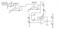
I have an op-amp circuit with two LM324's, one to combine the analog (stereo audio) signal, and the second to amplify to ~0.8v.
The next stage is a TLC339 comparator, which has an output of ~1.2, but the expected output is 5v when the signal is over the 0.25v
set point.

I am new to mixed signal design, and any help would be appreciated.
 

Attachments

DickCappels

Joined Aug 21, 2008
10,153
The TLC393 has open drain outputs. If your VCC is 10V then you should get +5V whenever the + input exceeds the - input.

How are you measuring the output (with a scope I hope)?
Is your Vcc = 10V?
 

Thread Starter

Mark Rice

Joined Feb 6, 2017
4
Vcc is 5 volts, and I removed R13 with the result of ~1 to 2 volts on the output of TLC339. Unfortunately I do not have a scope, instead using a DMM.
 

DickCappels

Joined Aug 21, 2008
10,153
Taking a broad leap here, if your input is an AC coupled signal the voltage will appear to be anything but +5V on the output of the comparator because the output will be continually changing and the digital multimeter will show the average value.

If you like, you can make a peak detecting probe using a small signal diode and a capacitor. The voltage across the capacitor will be a little less than the peak voltage, but it will give you a picture of what is going on. The error is likely to be 0.6 volts because of the forward voltage drop of the diode. For audio frequencies and a 10 Meg Ohm digital voltmeter a capacitor value around 0.1 uf should work fine.

upload_2018-11-19_10-13-31.png
 

danadak

Joined Mar 10, 2018
4,057
You can start with a PC sound card based scope for free. Will give you basically
audio range scope, spectrum analyzer, and function generator all using your
PC sound card. Note sound card inputs are AC coupled. But still useful.

https://www.zeitnitz.eu/scope_en

http://www.zelscope.com/

http://www.ledametrix.com/oscope/

http://www.virtins.com/downloads.shtml


But first build a simple circuit to protect sound card inputs so you do not
ruin from transients, overvoltage. Google "protect sound card input".


For example http://makezine.com/projects/sound-card-oscilloscope/


Sound card impedance bridge -

http://www.marucchi.it/ZRLC_web/ZRLC/Steber_An_LMS_Impedance_Bridge.pdf

http://www.sillanumsoft.org/ZRLC.htm


There is low cost logic analyzer, good to several Mhz, ~ $10
https://www.ebay.com/itm/USB-Logic-...270582?hash=item25f26191f6:g:Xs4AAOSwQ7haxEa1
https://www.saleae.com/downloads/


Search ebay for USB oscilloscope, quite a few offerings that will get you >> 1 Mhz.


And function generation and others -
http://www.radio.imradioha.org/pc_based_test_gear.htm


Regards, Dana.
 

Thread Starter

Mark Rice

Joined Feb 6, 2017
4

Attachments

MrChips

Joined Oct 2, 2009
30,706
Sorry. The photos are too dark and not sharp enough.
I cannot see the markings on the resistors.
I do not know which pins of the comparator are being used. You did not label the pins in your circuit schematic.
There are wires in the way and it is difficult to tell where the connections are made.
 

Bordodynov

Joined May 20, 2015
3,177
Look carefully at the input stage of the circuit. I do not like it. You cannot see how the operating point of the first op amp is set. Also not visible power operational amplifiers. Is it bipolar or from a single power source?
 

Thread Starter

Mark Rice

Joined Feb 6, 2017
4
Look carefully at the input stage of the circuit. I do not like it. You cannot see how the operating point of the first op amp is set. Also not visible power operational amplifiers. Is it bipolar or from a single power source?
This circuit is powered from a single source. I was busy with other projects, and may need to pick this up later.
Thanks for the replies so far.
 
Top