Comparator input bias current in STM32L0783 micro?

Thread Starter

eem2am

Joined Jul 22, 2012
40
Hi,
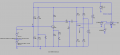
Do you believe that the attached LTspice simulation is the best way to analyse the effects of the input bias current in one of the comparators inside the STM32L073 (48 pin) microcontroller?

STM32L073 datasheet
https://www.st.com/en/microcontrollers-microprocessors/stm32l073rz.html

I believe the input bias current to each of the comparator input is +/-50nA (Pg 102 of datasheet)?
 

Attachments

Ian0

Joined Aug 7, 2020
13,097
I would just multiply the 50nA by the impedance that is driving the input, and that is the maximum voltage error.
The comparator has a input offset voltage of ±20mV which is poor in comparison to something as cheap as the LM339.
 

Thread Starter

eem2am

Joined Jul 22, 2012
40
Thanks, the input offset voltage is the voltage you have to put into it in order to get it to switch?....ie, 20mV away from the ref and it switches...instead of "at" the ref voltage?
 

Ian0

Joined Aug 7, 2020
13,097
Thanks, the input offset voltage is the voltage you have to put into it in order to get it to switch?....ie, 20mV away from the ref and it switches...instead of "at" the ref voltage?
Yes, but don't forget that it is a maximum value, so in reality it could be any value between -20mV and +20mV, with the likelyhood of any particular value following a normal distribution curve.
 

Thread Starter

eem2am

Joined Jul 22, 2012
40
Thanks
BTW, Do you know if this comparator input bias current is more likely to be coming into the comparator's input pin or out of it?
 

Thread Starter

eem2am

Joined Jul 22, 2012
40
Hi,
The attached comparator circuit takes in some pulsing and turns it into a rail to rail pulsing.
(LTspice and PNG attached)
However, when no pulses come, the signals at the input to the comparator are just 100mV apart.
Also, it is the comparator inside the STM32L073 microcontroller, which has unspecified input bias current,
which may be higher than the 50nA shown here.
Also, the input divider resistances are MegOhm+ and could vary with moisture/dirt ingress.
Would you say this is a reliable design.?
Academically speaking it works, but its shoddy and has no need to be like this.
The circuitry could be easily changed to make the pulsing be rail to rail to the comparator input for example.

Would you go forward with this?....specially since input bias current of the comparator is unknown and may be
significantly higher than the 50nA shown and result in those inputs being even closer in voltage when no pulsing?
 

Attachments

ericgibbs

Joined Jan 29, 2010
21,390
hi @eem2am

Could you please explain how you expect that asc simulation is intended to work?
Also, why are you trying to determine the input specification of the Comparator section.

Is this a College or Homework assignment.
E

BTW: check this image, what is the purpose of R9 and R10 ?
EG57_ 2810.gif
 
Top