common anode - PNP MOSFET

Thread Starter

daisyland773

Joined Nov 21, 2022
9
hello,
recently i've found a new hobby in simple DC electrical
as always a problem occured and i need help from elders in this realm.

english is not my strong language. especially technical words.

so please be patient..
here it goes,

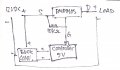
from the schematic, the problems are
12v and 5v converter come from the same source. that's why the mosfet is always on.

any simple suggestion how to fix this without adding new source?

with schematic would be awesome.
 

Attachments

AlbertHall

Joined Jun 4, 2014
12,345
You could use a circuit as shown below to level shift the HT12D outout. Where the circuit connects to +5V connect instead to your +12V and connect the output to your P-MOS gate.
1669106633207.png
 

Thread Starter

daisyland773

Joined Nov 21, 2022
9
As long as your 12V supply is stable,you can run the HT12D straight from that, without using the buck converter. You will still need to use the 2N7000 inverter to drive the P Channel Mosfet on and off, though.
unfortunately, the wireless rf receiver is at 5v max.. thank you for your suggestion..
 

Thread Starter

daisyland773

Joined Nov 21, 2022
9
Are all your grounds connected together?
ground and anode comes from the same source (12v to buck converter 5v to ht12d decoder). ht12d channel output can be anode or cathode.

i want to use pmos for the output. i've tried using 2 power source with connected cathode.
the gate on pmos works. but with only 1 power source, the gate stuck in always open.
 

BobTPH

Joined Jun 5, 2013
8,813
You should find an electronics glossary and learn the meaning of the various electronics related terms. Your usage is making it difficult to communicate effectively.
 

MrSalts

Joined Apr 2, 2020
2,767
You can use the
ground and anode comes from the same source (12v to buck converter 5v to ht12d decoder). ht12d channel output can be anode or cathode.

i want to use pmos for the output. i've tried using 2 power source with connected cathode.
the gate on pmos works. but with only 1 power source, the gate stuck in always open.
Did you connect it like this?
BA9515B1-CD29-473D-987A-49CEDC4D2132.png
 

MrSalts

Joined Apr 2, 2020
2,767
Did you connect both Mosfets like I have in the schematic?
Are you sure you understand the correct pin out of each Mosfet?
 

BobTPH

Joined Jun 5, 2013
8,813
With no signal, i.e, the input not connected to anything, it may be either on or off. No signal, does not mean the same thing as 0V or a low signal.
 
Top