Combining Power Banks

Thread Starter

Mud

Joined Aug 22, 2018
6
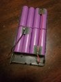
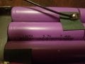
I have two 16,000 mAh power banks with 5V1A and 5V2.4A output ports on both. One circuit board was damaged, but the batteries are okay. If I solder it into the other circuit using parallel, will it function the same with twice as long of a life? And how will this affect the battery display? It's just 4 lights to simulate the charge level in increments of 25%. No, I don't know what kind of batteries they are.
 

ScottWang

Joined Aug 23, 2012
7,397
Normally I don't encourage you to in parallel with two batteries, because when one of the batteries is higher than the other one then the voltage lower one will be become a load for the voltage higher one, and that is no good for the battery usage life, If you in series two Schottky diodes for each battery and to connected together then it will be loss about 0.3V~0.4V and the Output voltage will be as 4.6V~4.7V.

Could you take a picture for the batteries and upload them as 800x600 *.jpg, you can use the button "Upload a File" to upload your files and that it is under the message box.
 

oz93666

Joined Sep 7, 2010
739
Yes that will almost certainly be OK if the voltage feeding the electronics is the same for both banks ...

The cells in these pacts are 18650s , they look the same shape , but are slightly larger than AA and output between about 3.3 and 4.2 V ...

The only way it will effect the charging display is it will just take longer to charge ....

Another approach , if you want to keep things neat is to remove and separate all the cells ,check the capacities , and put the best ones back into just one bank ..... you will probably find the capacities of the cells vary greatly ... often these are not new but have been removed from spent laptop batteries in china , and repackaged for use as a power bank.
 

ArakelTheDragon

Joined Nov 18, 2016
1,362
The way to overcome the charging problems is to connect the upper plus to the load and the lower minus to the load. That way even in parallel, the batteries will get charged and dicharged properly, but it will take at least 1 balancing charge before that, so they can have the same voltage.
 

oz93666

Joined Sep 7, 2010
739
The pictures appear to show Eight 3.7V 18650 cells connected in parellel so the output voltage is average 3.7V (varies from 3.3 to 4.2)
So you want to connect Sixteen in parallel which will give same voltage , twice the capacity and take twice as long to charge ....

To do this take the red wire from one pack and solder/connect to red wire of other pack.... Now you want to connect black to black .... trouble is the two packs are probably charged to different voltages ,If the voltages are too much apart you could get high current flowing. Touch the black wires together if they get very hot then the balancing current is probably over 15A ,you don't want to go too much over that , 8 cells can take 16A comfortably.... to keep the current low connect the black wires through a low resistance , a coil of wire .... Once the two packs have about the same voltage you can solder the the black wires together and jobs done.
 

Thread Starter

Mud

Joined Aug 22, 2018
6
So would I solder the wires of the new battery pack directly to the voltage output of the board for the first pack so there is two circuits of parallel, or would I open the circuit and make one large parallel circuit?
And can you please explain the coil of wire?
 

oz93666

Joined Sep 7, 2010
739
So would I solder the wires of the new battery pack directly to the voltage output of the board for the first pack so there is two circuits of parallel, or would I open the circuit and make one large parallel circuit?
And can you please explain the coil of wire?
just solder red from the new battery pack to red on the existing pack ...stay away from the electronics , solder on the battery ...

What do you have ??? a voltmeter ??? any resistors ??? wire ???what sort of wire???
 

Thread Starter

Mud

Joined Aug 22, 2018
6
.... to keep the current low connect the black wires through a low resistance , a coil of wire .... Once the two packs have about the same voltage you can solder the the black wires together and jobs done.
I was just wondering what you had meant by this
 

Thread Starter

Mud

Joined Aug 22, 2018
6
The input for both of these devices is micro USB. How hard would it be to de-solder that connection and put in a USB-C female receiver? I cannot find a pin schematic. This one isn't too important, mainly just curious. Thanks in advance
 
Top