Colpitts Oscillator Op Amp Help

Thread Starter

TipsEZ

Joined May 28, 2015
6
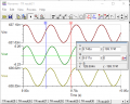
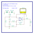
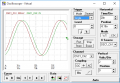
I'm having an issue here getting the correct Vout, or any Vout for that matter. What am I missing? With Rg at 403 ohms, I should be getting 5V out, but I'm not. Furthermore, if I set the scope down to a lower Voltage scale, I'm seeing a VERY noisy circuit.

Capture.JPG Capture.JPG
 

Thread Starter

TipsEZ

Joined May 28, 2015
6
Disregard the value for Rg in the image, it's set to 403 ohms as I stated, this was just a grab from me trying to see if I could effect any change on my V out by changing the value of Rg
 

Thread Starter

TipsEZ

Joined May 28, 2015
6
Thank you for the response. I've looked at that page for a few, but haven't had much luck in understanding the comparison of that page to what I've got going here. I've attached the document we are meant to use to draw our circuit. The assignment was to verify with various values of Rg we could get a specific Vout of 5V, 7.5V... etc.

EDIT: I should add that we had to calculate the values of Rg which is why I'm using Vout of 5V with Rg of 403 ohms as my example.
 

Attachments

GopherT

Joined Nov 23, 2012
8,009
Thank you for the response. I've looked at that page for a few, but haven't had much luck in understanding the comparison of that page to what I've got going here. I've attached the document we are meant to use to draw our circuit. The assignment was to verify with various values of Rg we could get a specific Vout of 5V, 7.5V... etc.

EDIT: I should add that we had to calculate the values of Rg which is why I'm using Vout of 5V with Rg of 403 ohms as my example.
Not working in simulation or not irking on a breadboard? If simulator, which one are you using. Not all will start oscillating on their own. You may need to add a seed value of some type or use another simulator.
 

Thread Starter

TipsEZ

Joined May 28, 2015
6
Not working in simulation. I'm using Multisim. In regards to the battery terminals on the op amp, I just verified that again and they are connected correctly (one of the first things I checked).

I hadn't thought about the need to give it a nudge... Just a simple step up pulse to get it started?
 

MikeML

Joined Oct 2, 2009
5,444
Here is a theoretical fix in four steps. Step 1 is your circuit minus the amplitude limiting. Note that with an initial pertubation, .ic I(L1)=10u, the oscillations die out, meaning that the loop gain is not sufficient.
108a.gif


Step2. I cant see any reason for R2 to be there, so I deleted it. Better, oscillations last longer, but still die out.

108b.gif

Step 3. Because C1 = C2, there is a voltage step up of two from the tap to V(n), therefore we can use a voltage follower (Gain of 1), and still have a loop gain of two, so getting rid of R3 should fix it.

108c.gif

Step 4. Sure enough, we now have sufficient loop gain for the oscillations to build up infinitely. Now is the time to put the amplitude limiter back:

108d.gif

I didn't check the specs on your opamp, but it will have to be a damn fast one to make a 8MHz oscillator.
 

Thread Starter

TipsEZ

Joined May 28, 2015
6
Thank you for the feedback. I'll drop R3 and see what I get. If it helps, we are working on RF amps; so the 8MHz freq sounds right. For fun, here's a link to the data sheet.

Just a quick glance at SR tells me it can handle the speeds. I scrolled down a bit and it looks to be solid to 10Mhz. But! I'm new to reading data sheets. I'm working to move from testing to designing and learning it's a much larger step than I'd expected.

http://www.ti.com/lit/ds/symlink/lm6181.pdf
 

Thread Starter

TipsEZ

Joined May 28, 2015
6
So I just changed my feedback resistor to a value of 0 and now I'm getting a pretty ugly waveform out, as opposed to the sin wave I'm hoping for. Attached is a shot of the waveform.

Also, what program are you using, it looks to be much cleaner than what I'm running. Capture0.JPG
 

JoeJester

Joined Apr 26, 2005
4,390
According to the "design idea's" pdf that you provided, Rg is used to increase the gain of your opamp.

Start your transition analysis at zero volts. I had the simulated oscillations reaching maximum in less than 10 microseconds.

Attached are the results. I set the Rg (R5 on my schematic) value of 130 to get closer to their output of 12 volts pk-pk at the output of the op amp. All resistors were the E24 series.

The oscillator frequency was slightly lower that what they observed, but remember, the simulator may not be as you observed. It should be close.
 

Attachments

Last edited:
Top