clearing a fault, using a schmitt trigger a mosfet and a mechanical switch

Thread Starter

newbieateverything

Joined Feb 25, 2013
95
Sorry i was told what
i dont get you

do you mind telling me again
i am just trying to understand what i have built so far

how does a mosfet absorb the energy
 
Last edited:

shortbus

Joined Sep 30, 2009
10,049
hi, again
i just realised the circuit we have been doing is actually only a mosfet switch
its not a hybrid between a mechanical breaker and a mosfet which is what i was trying to do.
This is what you've been told.

Avalanche is really called, 'avalanche BREAKDOWN'. It is, like most breakdowns, something you don't want. The avalanche breakdown on the data sheet is the maximum voltage that can go through the D/S before the mosfet is destroyed. You are supposed to keep your circuit design below that number. A good number is ~ 1/2 of the value shown. A good design will never use components at the maximum values, always have a margin of error figured in.
 
Last edited:

Ron H

Joined Apr 14, 2005
7,063
Avalanche has nothing to do with this circuit, and the MOSFET absorbs very little energy. It simply goes from a near short circuit to an open circuit a few hundred nanoseconds after the fault is detected.

What do you mean by the expression "a hybrid between a mechanical breaker and a mosfet"?
 

Thread Starter

newbieateverything

Joined Feb 25, 2013
95
I mean to say the circuit you designed is a Mosfet switch
I was trying to design a hybrid circuit breaker
which is a solid state circuit breaker+ a mechanical circuit breaker
The mosfet switch connection is going to be my SCB

i believe the circuit you designed still needs an extra mechanical switch in series or in parallel if the circuit you designed is to be called a hybrid

i hope this makes sense

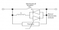
the picture attached is a hybrid circuit breaker it includes a mechanical circuit breaker and a mosfet switch which is the solid state circuit breaker

The circuit you designed lacks the Mechanical switch, it only has a switch that closes to cause the fault.
 

Attachments

Last edited:

Thread Starter

newbieateverything

Joined Feb 25, 2013
95
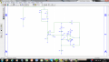
Hey Ron so i am having a problem testing the circuit.
My complementary output Q simply gives me a high of 10, so my Mosfet isn't switching this problem has followed me for the past 2 days.
I am properly feeding an adequate clock signal of ± 5 directly from a signal gen just to make sure yet it still doesn't work

on another note. I know we have discussed this at length previously
however how do i set the trigger values to -1V and 3V based on this schematic
Just in case i can't fix the problem with the flip flop or even if i can just want to know i can do it both ways.

About the hybrid stuff don't worry about that.
 

Attachments

Ron H

Joined Apr 14, 2005
7,063
Hey Ron so i am having a problem testing the circuit.
My complementary output Q simply gives me a high of 10, so my Mosfet isn't switching this problem has followed me for the past 2 days.
I am properly feeding an adequate clock signal of ± 5 directly from a signal gen just to make sure yet it still doesn't work

on another note. I know we have discussed this at length previously
however how do i set the trigger values to -1V and 3V based on this schematic
Just in case i can't fix the problem with the flip flop or even if i can just want to know i can do it both ways.

About the hybrid stuff don't worry about that.
You are misinformed. The MOSFET needs Vgs=0v to turn it off, and Vgs=10v to turn it on.
I am properly feeding an adequate clock signal of ± 5 directly from a signal gen just to make sure yet it still doesn't work
Where are you applying ±5V? If it is to the flip-flop, you have probably destroyed it. The FF also needs 0V and vcc (10v in my circuit) for all logic inputs.
 

Ron H

Joined Apr 14, 2005
7,063
I mean to say the circuit you designed is a Mosfet switch
I was trying to design a hybrid circuit breaker
which is a solid state circuit breaker+ a mechanical circuit breaker
The mosfet switch connection is going to be my SCB

i believe the circuit you designed still needs an extra mechanical switch in series or in parallel if the circuit you designed is to be called a hybrid

i hope this makes sense

the picture attached is a hybrid circuit breaker it includes a mechanical circuit breaker and a mosfet switch which is the solid state circuit breaker

The circuit you designed lacks the Mechanical switch, it only has a switch that closes to cause the fault.
There is no MOSFET in the circuit you posted.:confused:
 

Thread Starter

newbieateverything

Joined Feb 25, 2013
95
you talking about the hybrid circuit yes i couldn't find one with a mosfet
the one i posted uses IGCt's i think

if you talking about the schematic after please look again the circuit has the IRF150 mosfet

sorry was not feeding a clock of + or - 5V to my clock input was simply feeding a pulse of 5v in amplitude.
from my signal gen.the flip flop is unharmed, still works just fine
However at my complementary output vs getting a voltage pulse of 10 i get only a voltage pulse of 1V

Incase i got this wrong what should i be feeding into the clock singal if i am using a signal gen

i built another one to test it.
 

Ron H

Joined Apr 14, 2005
7,063
you talking about the hybrid circuit yes i couldn't find one with a mosfet
the one i posted uses IGCt's i think

if you talking about the schematic after please look again the circuit has the IRF150 mosfet

sorry was not feeding a clock of + or - 5V to my clock input was simply feeding a pulse of 5v in amplitude.
from my signal gen.the flip flop is unharmed, still works just fine
However at my complementary output vs getting a voltage pulse of 10 i get only a voltage pulse of 1V

Incase i got this wrong what should i be feeding into the clock singal if i am using a signal gen

i built another one to test it.
As I said in my previous post,
The FF also needs 0V and vcc (10v in my circuit) for all logic inputs.
 
Top